
Machining device capable of automatically edgewise chamfering and polishing iron cartoon pendant

A technology for processing equipment and pendants, which is applied in the field of automatic edge chamfering and grinding iron cartoon pendant processing equipment, which can solve problems such as inaccurate grinding, long processing time, and pendant damage, and achieve the effect of increasing work efficiency

Inactive Publication Date: 2021-01-26
DONGGUAN UNIV OF TECH
View PDF0 Cites 4 Cited by
  • Summary
  • Abstract
  • Description
  • Claims
  • Application Information

AI Technical Summary

Problems solved by technology

[0004] Aiming at the deficiencies of the prior art, the present invention provides an iron cartoon pendant processing equipment equipped with automatic edge chamfering and grinding, which solves the problem that the surrounding corners of the pendant need to be processed after the iron pendant proposed in the background technology is stamped and formed. Grinding can not only be beautiful, but also avoid burrs from scratching the skin and causing physical damage. However, due to the different shapes of the pendants, artificial hands and grinding guns are used to polish the surrounding corners of the pendants. Due to the time required for manual grinding of a single piece of processing It is long, and you need to be very focused when polishing. As a result, the body will be tired for a long time, resulting in inaccurate polishing and damage to the performance of the pendant.

Method used


Image

  • Machining device capable of automatically edgewise chamfering and polishing iron cartoon pendant
  • Machining device capable of automatically edgewise chamfering and polishing iron cartoon pendant
  • Machining device capable of automatically edgewise chamfering and polishing iron cartoon pendant

Examples


Embodiment Construction

[0029] The following will clearly and completely describe the technical solutions in the embodiments of the present invention with reference to the accompanying drawings in the embodiments of the present invention. Obviously, the described embodiments are only some, not all, embodiments of the present invention.

[0030] In the description of the present invention, unless otherwise stated, the meaning of "plurality" is two or more; the terms "upper", "lower", "left", "right", "inner", "outer" , "front end", "rear end", "head", "tail", etc. indicate the orientation or positional relationship based on the orientation or positional relationship shown in the drawings, and are only for the convenience of describing the present invention and simplifying the description, rather than Indicates or implies that the device or element referred to must have a particular orientation, be constructed and operate in a particular orientation, and therefore should not be construed as limiting the...


PUM


Abstract

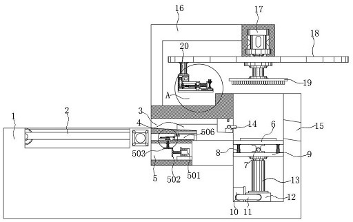
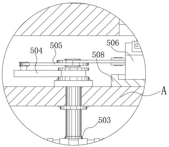
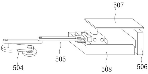
The invention discloses a machining device capable of automatically edgewise chamfering and polishing an iron cartoon pendant. The machining device comprises a polishing case; a pendant transfer beltis installed in a left case body of the polishing case; a bottom bolt of a rotary plate is fixedly provided with a pendant fixing pressure plate; and a chamfering polishing head is fixedly clamped tothe output end of a servo motor. When an automatic telescoping assembly and the pendant fixing pressure plate are arranged in the bottom center and on the outer side of the rotary plate respectively,it is convenient for the pendant fixing pressure plate to cooperate with an operation table to press the pendant due to the arrangement of the pendant fixing pressure plate; and through the componentsof a protruding button and a first spring, it is convenient for the protruding button to be fit for the surfaces of the pendants of different structures, so that a clamping fixing structure is formed. Through the arrangement of an automatic telescoping assembly, a chamfering polishing head is conveniently driven to be fit for the pendant, so that memory polishing is facilitated, and the damage, caused when an operator is absent-minded during manual polishing, to the workpiece is prevented. Therefore, automatic machining is easy to achieve; and the working efficiency is improved.

Description

technical field [0001] The invention relates to the technical field of pendant grinding, in particular to a processing equipment for iron cartoon pendants with automatic edge chamfering and grinding. Background technique [0002] Pendants belong to the category of decorations, which are generally used to beautify personal appearance, or to decorate living rooms, beautify public environments, and decorate cars. Development, began to transform into the modification part, and derived various decorations mainly based on modification. Jewelry is used to decorate and wear. Chains are used together. Although there are various materials, they are generally used for decoration on key chains or necks and wrists. [0003] The shapes, patterns, and materials of pendants vary according to everyone's preferences, and some iron pendants need to be polished around the corners of the pendant after stamping, so as to be beautiful and avoid burrs from scratching the skin and causing physical ...

Claims


Application Information

Patent Timeline
Patent Type & Authority Applications(China)
IPC IPC(8): B24B9/00B24B27/00B24B41/00B24B41/06B24B41/02B24B47/06
CPCB24B9/00B24B27/0046B24B41/005B24B41/02B24B41/06B24B47/06
Inventor 林朝阳
Owner DONGGUAN UNIV OF TECH
Learn More