

Short-radius drilling tool
A short-radius drilling and tool technology, applied in the field of drilling, can solve the problems of long deflection section, small wellbore curvature, large wellbore curvature, etc., and achieve the effect of shortening the length, eliminating a lot of space and the hidden dangers brought by
- Summary
- Abstract
- Description
- Claims
- Application Information
AI Technical Summary
Problems solved by technology
Method used
Image

Examples
Embodiment approach 1
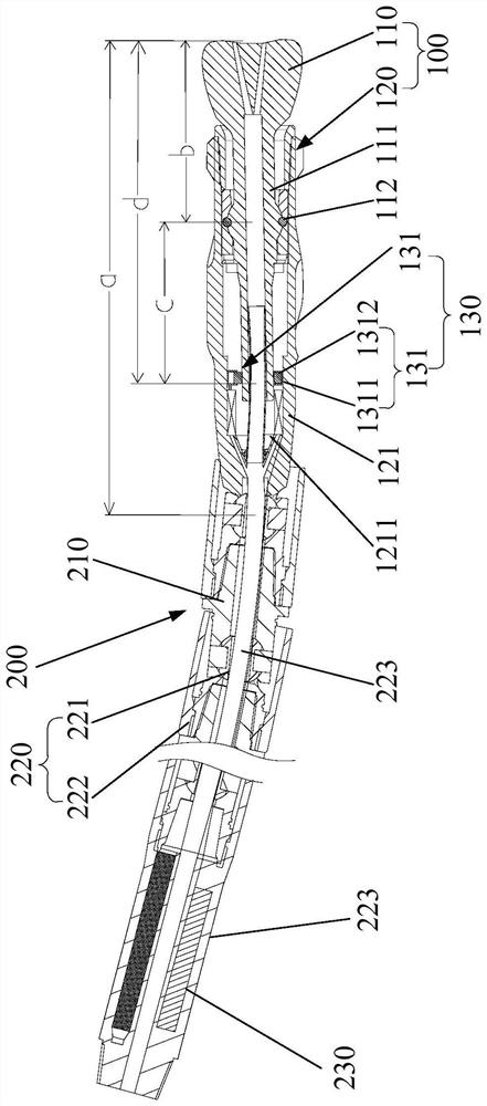
[0077]Such asfigure 1 As shown, the upper end of the drill bit 110 is coaxially connected with a transmission lever 111. Specifically, the transmission lever 111 is cylindrical, and the transmission lever 111 penetrates the inside of the carrier body 121. Preferably, the transmission lever 111 and the drill bit 110 are integrated Structure, or, the transmission lever 111 is welded and connected to the upper end of the drill bit 110, the transmission lever 111 is connected to the lower part of the carrier body 121 through the controllable universal joint 112, and a movable gap is formed between the transmission lever 111 and the carrier body 121 to deflect The guiding mechanism 130 is arranged in the movable gap and above the controllable universal joint 112. The driving piston 1312 can abut against the well wall through the transmission lever 111, and the expansion and contraction of the driving piston 1312 can drive the transmission lever 111 around the controllable universal joint...
Embodiment approach 2
[0083]Such asfigure 2 As shown, the driving hydraulic cylinder 131 is arranged below the weight-on-bit torque deflection transmission mechanism 220 connected to the carrying body 121, and the distance from the setting position of the driving hydraulic cylinder 131 to the drill bit 110 is smaller than that of the driving hydraulic cylinder 131 to the carrying body 121. The distance between the connected WOB torque deflection transmission mechanism 220, so that the point of action of the thrust force is closer to the drill bit 110 and away from the turning point, so as to drive the drill bit 110 to deflect in the guiding direction;
[0084]The electric drive actuator 140 includes a rotary valve 141 and a drive motor 142. The carrying body 121 is provided with a through flow passage 1211. The rotary valve 141 can periodically connect the through flow passage 1211 with the driving hydraulic cylinder 131 so that the driving piston 1312 can be As the drill string rotates, it periodically abu...
Embodiment approach 3
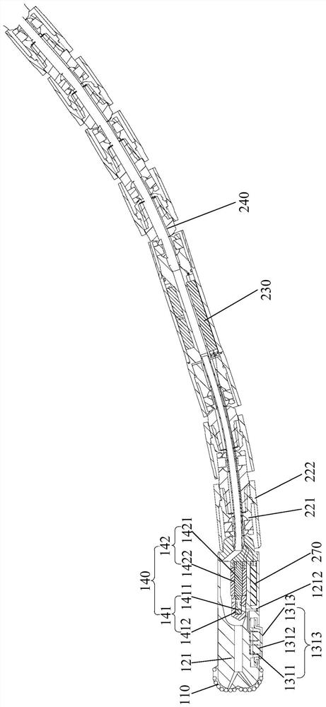
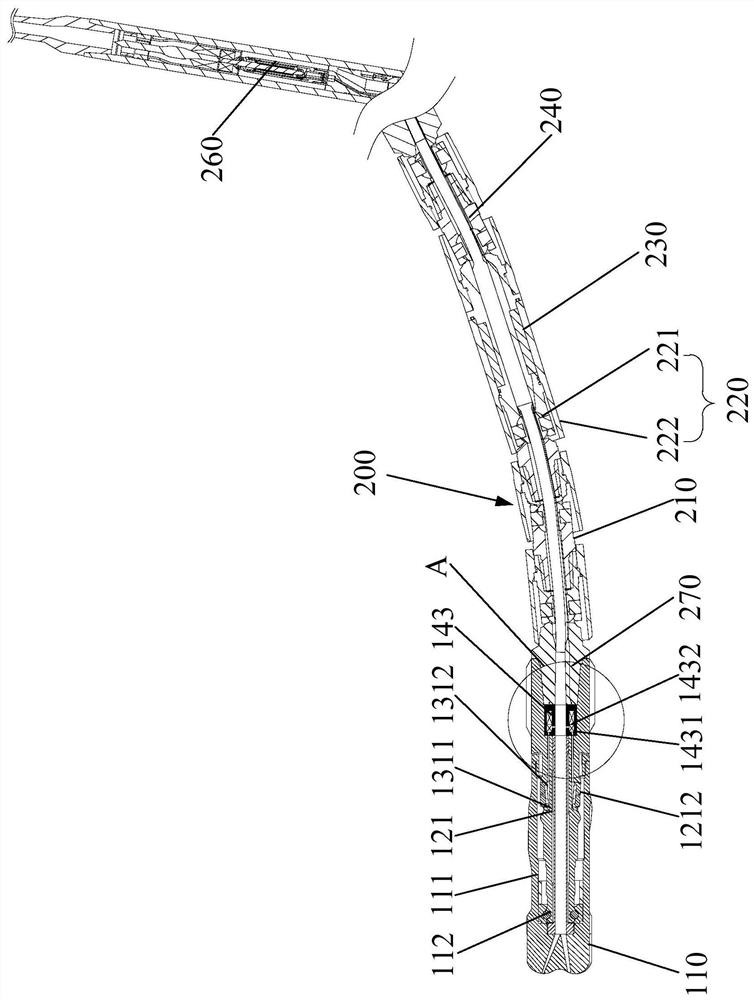
[0088]Such asimage 3 withFigure 4 As shown, the driving hydraulic cylinder 131 is arranged below the weight-on-bit torque deflection transmission mechanism 220 connected to the carrying body 121, and the distance from the setting position of the driving hydraulic cylinder 131 to the drill bit 110 is smaller than that of the driving hydraulic cylinder 131 to the carrying body 121. The distance between the connected WOB torque deflection transmission mechanism 220, so that the point of action of the thrust force is closer to the drill bit 110 and away from the turning point, so as to drive the drill bit 110 to deflect in the guiding direction;
[0089]The electric drive actuator 140 includes a rotary valve 141 and a drive motor 142. The carrier body 121 is provided with a through flow passage 1211. The rotary valve 141 can periodically communicate with the drive hydraulic cylinder 131 through the through flow passage 1211. The drive motor 142 is electrically driven The actuator drive con...
PUM
 Abstract
Description
Claims
Application Information