Compression release type engine cylinder internal braking device

A technology for engine cylinders and braking devices, which is applied in the direction of engine components, machines/engines, valve devices, etc., can solve problems such as delay in opening and closing, impact on vehicle braking performance, cracking of hydraulic oil chambers, etc., to achieve volume reduction and weight, fast response, and improved braking power

Pending Publication Date: 2021-01-26
ZHEJIANG QIANGNENG MOTIVITY
View PDF2 Cites 1 Cited by
  • Summary
  • Abstract
  • Description
  • Claims
  • Application Information

AI Technical Summary

Problems solved by technology

The technical solution of the above-mentioned patent is to adopt a hydraulic brake mechanism, which has the following defects: 1. Slow response speed, delay in opening and closing; 2. Affected by oil temperature and oil pressure, the plunger stroke changes and When the engine rotates at high speed, the oil pressure is too high, which will easily cause the hydraulic oil chamber to crack, and the engine brake will be forced to close, etc., which will affect the braking performance of the vehicle.

Method used


Image

  • Compression release type engine cylinder internal braking device
  • Compression release type engine cylinder internal braking device
  • Compression release type engine cylinder internal braking device

Examples


Embodiment Construction

[0025] Below in conjunction with accompanying drawing and specific embodiment the present invention will be described in further detail:

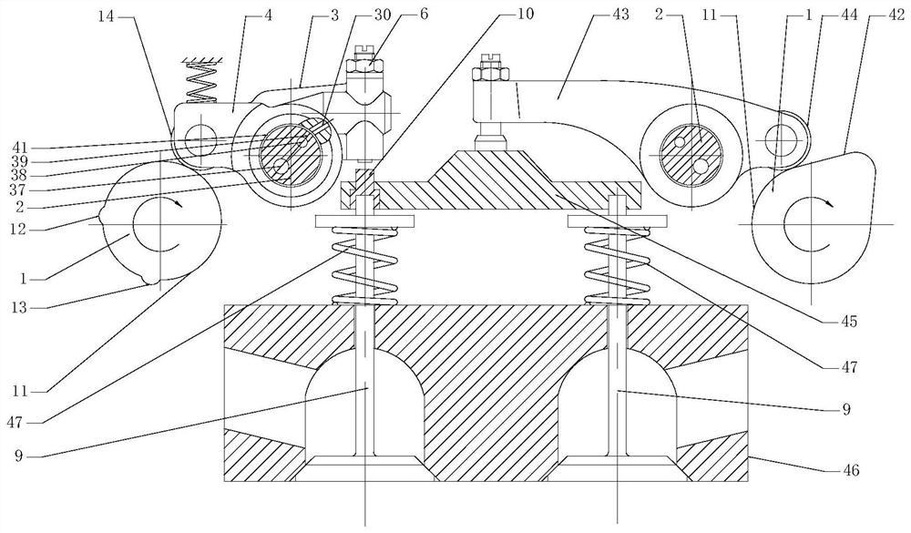
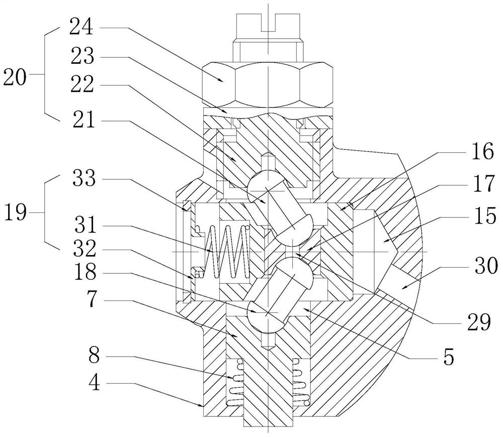
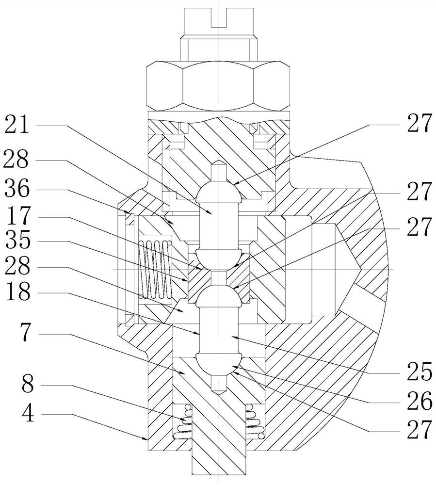
[0026] see Figure 1 to Figure 5 The present invention provides a compression-release type engine in-cylinder brake device, which includes a driving force input camshaft 1, and a brake rocker arm assembly 3 driven by the driving force input camshaft 1 to rotate and swing around a rocker arm shaft 2. The brake rocker arm assembly 3 includes a brake rocker arm 4 and a valve clearance control mechanism 6 arranged in the mounting hole 5 of the brake rocker arm 4. The valve clearance control mechanism 6 includes a brake plunger 7, a brake plunger 7 The return spring 8 with upward elastic force and the driving device with axial downward force on the brake plunger 7, the brake plunger 7 is facing the exhaust valve 9, when the brake plunger 7 is at the bottom dead center And when the distance between the brake plunger 7 and the valve cap 10 of the...


PUM


Abstract

The invention discloses a compression release type engine cylinder internal braking device. The compression release type engine cylinder internal braking device comprises a driving force input cam shaft and a braking rocker arm assembly which is driven by the driving force input cam shaft and can rotate and swing around a rocker arm shaft; the braking rocker arm assembly comprises a braking rockerarm and a valve clearance control mechanism arranged in an installation hole of the braking rocker arm; the valve clearance control mechanism comprises a braking plunger, a reset spring and a drivingdevice, wherein the reset spring has upward elastic force on the braking plunger, and the driving device has downward acting force in the axial direction on the braking plunger; and the braking plunger right faces an exhaust valve. A driving piston of the compression release type engine cylinder internal braking device synchronously drives an upper connecting rod and a lower connecting rod to swing, due to the fact that spherical heads of the upper connecting rod and the lower connecting rod conduct twisting actions in corresponding spherical grooves, the upper connecting rod downwards extrudes a middle sliding block in the swinging and twisting process, then the middle sliding block extrudes the lower connecting rod, the lower connecting rod downwards extrudes the braking plunger, accordingly, the braking plunger moves downwards, a valve cap is triggered, and accordingly engine cylinder internal braking work is achieved.

Description

technical field [0001] The invention belongs to the technical field of engines, and in particular relates to a compression release type engine cylinder braking device. Background technique [0002] In the prior art, the method of using the engine as a braking means is well known. After the oil supply of the engine is stopped, the engine output by power is temporarily converted into a compressor for absorbing power. When the fuel is cut off, the gas inhaled into the cylinder during the intake stroke of the engine is compressed during the compression stroke, and the exhaust valve is opened at or near the end of the compression stroke of the engine piston, the compressed gas is released, and the engine is compressed during the compression stroke. The energy absorbed by the compressed gas cannot be returned to the engine in the subsequent expansion stroke, but dissipated through the exhaust system of the engine. The end result is that the engine absorbs the energy of the vehicle...

Claims


Application Information

Patent Timeline
Patent Type & Authority Applications(China)
IPC IPC(8): F01L13/06F01L1/46
CPCF01L1/46F01L13/065
Inventor 吴广仓胡炳珍
Owner ZHEJIANG QIANGNENG MOTIVITY
Why Eureka
Try Eureka