Supercharge Your Innovation With Domain-Expert AI Agents!

Garbage self-heating type continuous pyrolysis device

A self-heating and garbage technology, applied in lighting and heating equipment, combustion methods, combustion types, etc., can solve the problems of low utilization rate of pyrolysis gas and slow waste disposal speed, and achieve the goal of increasing speed and utilization rate Effect

Pending Publication Date: 2021-01-26
JIANGHAN UNIVERSITY +1
View PDF0 Cites 0 Cited by
  • Summary
  • Abstract
  • Description
  • Claims
  • Application Information

AI Technical Summary

Problems solved by technology

[0003] However, when the existing waste pyrolysis equipment pyrolyzes waste, there are problems that the utilization rate of pyrolysis gas is not high and the speed of waste treatment is slow

Method used


Image

  • Garbage self-heating type continuous pyrolysis device
  • Garbage self-heating type continuous pyrolysis device
  • Garbage self-heating type continuous pyrolysis device

Examples


Embodiment 1

[0061] The basic structure of the garbage self-heating continuous pyrolysis device in this embodiment adopts the structure of the garbage self-heating continuous pyrolysis device in the specific embodiment.

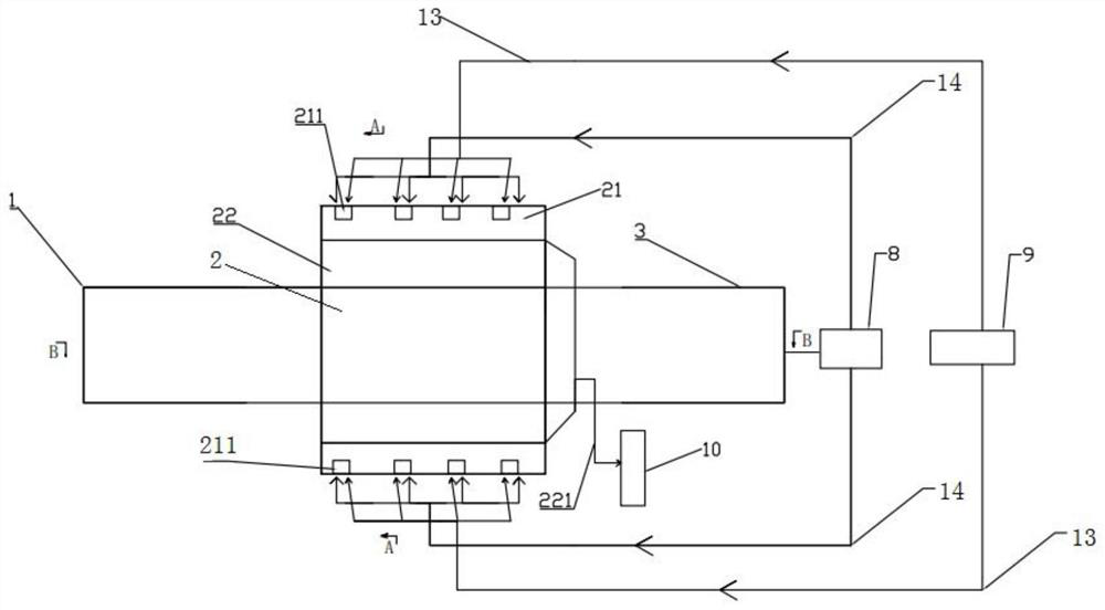
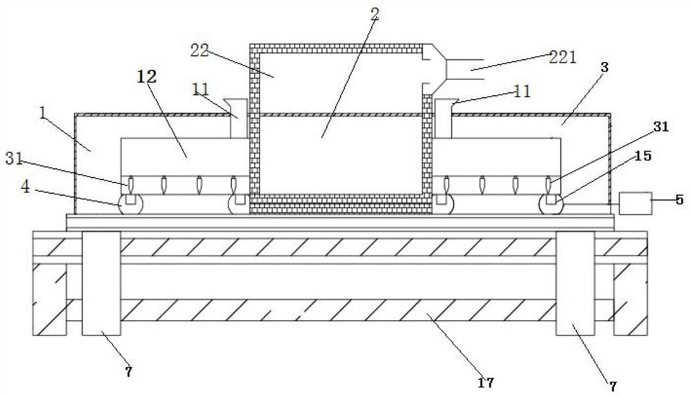
[0062] Furthermore, the combustion chamber and the flue gas chamber are rapidly assembled furnace walls on site, which are composed of metal frames and masonry. The wall is installed on the metal bracket connected to the steel beam of the combustion furnace. The weight of the wall is transmitted to the frame of the combustion furnace through the steel member. L*W*H (length, width, height, the same below) is 6.0m*2.0m*1.5m. The size L*W*H of the pyrolysis furnace is 19.0m*1.0m*1.0m, and the size L*W*H of the pyrolysis zone is 6.0m*1.0m*1.0m. The L*W*H of the mobile garbage truck is 6.0m*0.8m*0.3m.

[0063] A water-cooled jacket can be designed around the inlet of the first material zone 1 or the second material zone 3 of the pyrolysis furnace to prevent the waste in the ...

Embodiment 2

[0065] The combustion chamber and flue gas chamber are quick-fit furnace walls on site, consisting of metal frames and masonry. The wall is installed on the metal bracket connected to the steel beam of the combustion furnace. The weight of the wall is transmitted to the frame of the combustion furnace through the steel member. The size L*W*H (length, width, height, the same below) of the flue gas chamber 22 is 4.0m*2.0m*1.5m. The size L*W*H of the pyrolysis furnace is 12.5m*1.0m*1.0m, and the size L*W*H of the pyrolysis zone is 4.0m*1.0m*1.0m. The L*W*H of the mobile garbage truck is 4.0m*0.8m*0.4m.

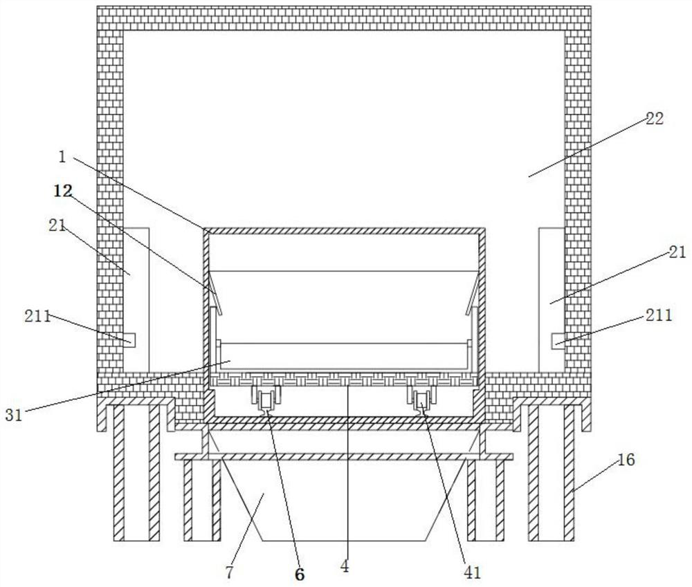
[0066] In the garbage self-heating continuous pyrolysis device of the present invention, the garbage trolley located in the first material area 1 is pushed to the pyrolysis area 2 under the action of the hydraulic propulsion mechanism 4. The discharge valve of the garbage hopper near the solution area 2 is opened, and the garbage gradually falls into the garbage trolley during ...


PUM


Abstract

The invention relates to a garbage self-heating type continuous pyrolysis device. The garbage self-heating type continuous pyrolysis device comprises a pyrolysis furnace, a flue gas chamber, a combustion chamber, a first loading mechanism, a second loading mechanism, a first propelling mechanism, a second propelling mechanism and a first fan. The pyrolysis furnace penetrates through the flue gas chamber, and the combustion chamber is arranged in the flue gas chamber. The pyrolysis furnace sequentially comprises a first material area, a pyrolysis area and a second material area from left to right, and the flue gas chamber surrounds the pyrolysis area. A guide rail is arranged at the bottom of the pyrolysis furnace and penetrates through the first material area, the pyrolysis area and the second material area. The first loading mechanism is connected with the first propelling mechanism. The second loading mechanism is connected with the second propelling mechanism, and the second propelling mechanism is arranged outside the pyrolysis furnace. According to the garbage self-heating type continuous pyrolysis device, the utilization rate of pyrolysis gas is increased while the garbage treatment speed is increased.

Description

technical field [0001] The invention relates to the field of garbage treatment, in particular to a self-heating continuous pyrolysis device for garbage. Background technique [0002] Pyrolysis refers to the process of decomposing, breaking and recombining the molecular chains of organic matter under the condition of anaerobic or anoxic. Among various domestic waste treatment schemes, pyrolysis is a treatment method that has attracted much attention at present, and can effectively solve various problems caused by traditional domestic waste treatment schemes. The garbage pyrolysis method is to turn domestic garbage into tar, combustible gas and coke by raising the temperature to above 500°C under the condition of isolating oxygen. During the pyrolysis process, the carbon-containing substances in domestic waste are decomposed into small molecular hydrocarbon gases, combustible gases, aromatic hydrocarbons, organic acids, etc. The advantages of the garbage pyrolysis treatment ...

Claims


Application Information

Patent Timeline
Patent Type & Authority Applications(China)
IPC IPC(8): F23G5/027F23G5/16F23G5/44F23G5/50
CPCF23G5/027F23G5/16F23G5/44F23G5/444F23G5/50F23G2201/30F23G2202/103
Inventor 米铁王新聂港张武竹辛善志黄芳
Owner JIANGHAN UNIVERSITY
Features
  • R&D
  • Intellectual Property
  • Life Sciences
  • Materials
  • Tech Scout
  • Unparalleled Data Quality
  • Higher Quality Content
  • 60% Fewer Hallucinations
Learn More