Supercharge Your Innovation With Domain-Expert AI Agents!

Method and device for acquiring bending moment of plate

An acquisition method and acquisition device technology, applied in the field of acquisition of plate bending moment, can solve the problems of inability to calculate the change of bending force, inaccurate acquisition of plate bending force, inaccurate metal plate bending force, etc., and achieve high accuracy Effect

Pending Publication Date: 2021-01-26
CRRC YANGTZE CO LTD
View PDF0 Cites 0 Cited by
  • Summary
  • Abstract
  • Description
  • Claims
  • Application Information

AI Technical Summary

Problems solved by technology

[0003] However, the existing sheet metal bending force is usually calculated based on the tensile strength of the sheet metal, which can only be calculated in an approximate manner. Moreover, it is impossible to calculate the change of the bending force during the forming process, because the bending force is affected by the bending force of the sheet metal. change in process
Unable to accurately obtain the bending force of the sheet
[0004] However, the bending force obtained by the existing method is inaccurate

Method used


Image

  • Method and device for acquiring bending moment of plate
  • Method and device for acquiring bending moment of plate
  • Method and device for acquiring bending moment of plate

Examples


Embodiment 1

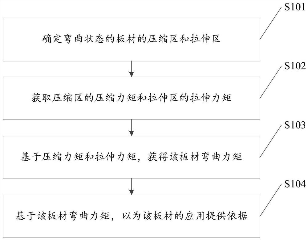
[0053] An embodiment of the present invention provides a method for obtaining the bending moment of a plate, such as figure 1 shown, including:

[0054] S101, determining the compression zone and the tension zone of the plate in the bending state.

[0055] S102. Obtain the compression moment in the compression zone and the tension moment in the tension zone.

[0056] S103. Obtain the plate bending moment based on the compressive moment and the tensile moment.

[0057] S104, providing a basis for the application of the plate based on the bending moment of the plate.

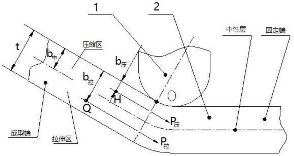
[0058] First, in S101, determine the compression zone and tension zone of the plate in the bending state, including:

[0059] Such as figure 2 As shown, the sheet is first presented in a bent state, specifically, one end of the sheet is fixed, and the other end is formed. Therefore, the formed plate in the bent state includes a bending fulcrum O in the middle, a fixed end at one end and a forming end at the ...

Embodiment 2

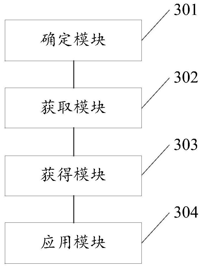
[0094] Based on the same inventive concept, the present invention also provides a device for obtaining the bending moment of the plate, such as image 3 shown, including:

[0095] A determining module 301, configured to determine the compression zone and tension zone of the sheet material in the bending state based on the bending fulcrum of the sheet material in the bending state;

[0096] An acquisition module 302, configured to acquire the compression moment in the compression zone and the tension moment in the tension zone;

[0097] An obtaining module 303, configured to obtain the plate bending moment based on the compressive moment and the tensile moment;

[0098] The application module 304 is configured to provide a basis for the application of the plate based on the bending moment of the plate.

[0099] In an optional implementation manner, the determining module 301 includes:

[0100] A first determining unit, configured to determine the fixed end and the forming en...

Embodiment 3

[0124] Based on the same inventive concept, Embodiment 3 of the present invention provides an electronic device, such as Figure 4 As shown, it includes a memory 404 , a processor 402 , and a computer program stored in the memory 404 and operable on the processor 402 , and the processor 402 implements the step of obtaining the bending moment of the plate when executing the program.

[0125] Among them, in Figure 4 In, bus architecture (represented by bus 400), bus 400 may include any number of interconnected buses and bridges, bus 400 will include one or more processors represented by processor 402 and various types of memory represented by memory 404 circuits linked together. The bus 400 may also link together various other circuits, such as peripherals, voltage regulators, and power management circuits, etc., which are well known in the art and thus will not be further described herein. The bus interface 406 provides an interface between the bus 400 and the receiver 401 a...


PUM


Abstract

The invention relates to the technical field of plate application, in particular to a method and device for acquiring the bending moment of a plate. The method comprises the steps: determining a compression area and a stretching area of a plate in a bent state; obtaining the compression torque of the compression area and the stretching torque of the stretching area; based on the compression momentand the stretching moment, obtaining the bending moment of the plate; and based on the bending moment of the plate, providing a basis for application of the plate. Since the bending moment is constant, the bending force is obtained according to the bending moment, and based on the bending force, a basis is provided for application of the plate, and the accuracy is higher.

Description

technical field [0001] The invention relates to the technical field of plate application, in particular to a method and a device for obtaining the bending moment of a plate. Background technique [0002] According to the bending force of the metal sheet, it can provide help for mold design and selection of bending equipment. [0003] However, the existing sheet metal bending force is usually calculated based on the tensile strength of the sheet metal, which can only be calculated in an approximate manner. Moreover, it is impossible to calculate the change of the bending force during the forming process, because the bending force is affected by the bending force of the sheet metal. changes in the process. The bending force of the sheet cannot be accurately obtained. [0004] However, the bending force of the metal plate obtained by the existing method is inaccurate. [0005] Therefore, how to provide accurate basis for mold design and selection of bending equipment is a te...

Claims


Application Information

Patent Timeline
Patent Type & Authority Applications(China)
IPC IPC(8): G06F30/17G06F30/20G06F119/14
CPCG06F30/17G06F30/20G06F2119/14
Inventor 吴代年成光张兴松刘华学柴林叶国华邹侃张锋毅沈磊李威
Owner CRRC YANGTZE CO LTD
Features
  • R&D
  • Intellectual Property
  • Life Sciences
  • Materials
  • Tech Scout
  • Unparalleled Data Quality
  • Higher Quality Content
  • 60% Fewer Hallucinations
Learn More