Eureka AIR delivers breakthrough ideas for toughest innovation challenges, trusted by R&D personnel around the world.

A direct-current brush motor and cooling fan

A DC brushed motor and brush technology, which is applied to the cooling of the engine, electromechanical devices, electrical components, etc., to achieve the effect of reducing power consumption and cost

Inactive Publication Date: 2021-01-26
东风博泽汽车系统有限公司
View PDF3 Cites 2 Cited by
  • Summary
  • Abstract
  • Description
  • Claims
  • Application Information

AI Technical Summary

Problems solved by technology

[0002] Cooling fans are generally used in automobile engines, but due to the compact interior space of automobile engine compartments, the axial length of the cooling fan motor is required to be as short as possible; therefore, due to the limitation of environmental components, the shape of the cooling fan motor is flat. At the same time, considering As far as the internal structure of the brushed motor is concerned, the current common design can only adopt the design method of four (two pairs) brushes, and the four brushes are evenly distributed at 360°. Smooth operation, the number of pairs of magnetic poles set on the stator is the same as the number of pairs of brushes, that is, the same design method of setting four (two pairs) of magnetic poles

Method used


Image

  • A direct-current brush motor and cooling fan
  • A direct-current brush motor and cooling fan
  • A direct-current brush motor and cooling fan

Examples


Embodiment Construction

[0025] The principles and features of the present invention are described below in conjunction with the accompanying drawings, and the examples given are only used to explain the present invention, and are not intended to limit the scope of the present invention.

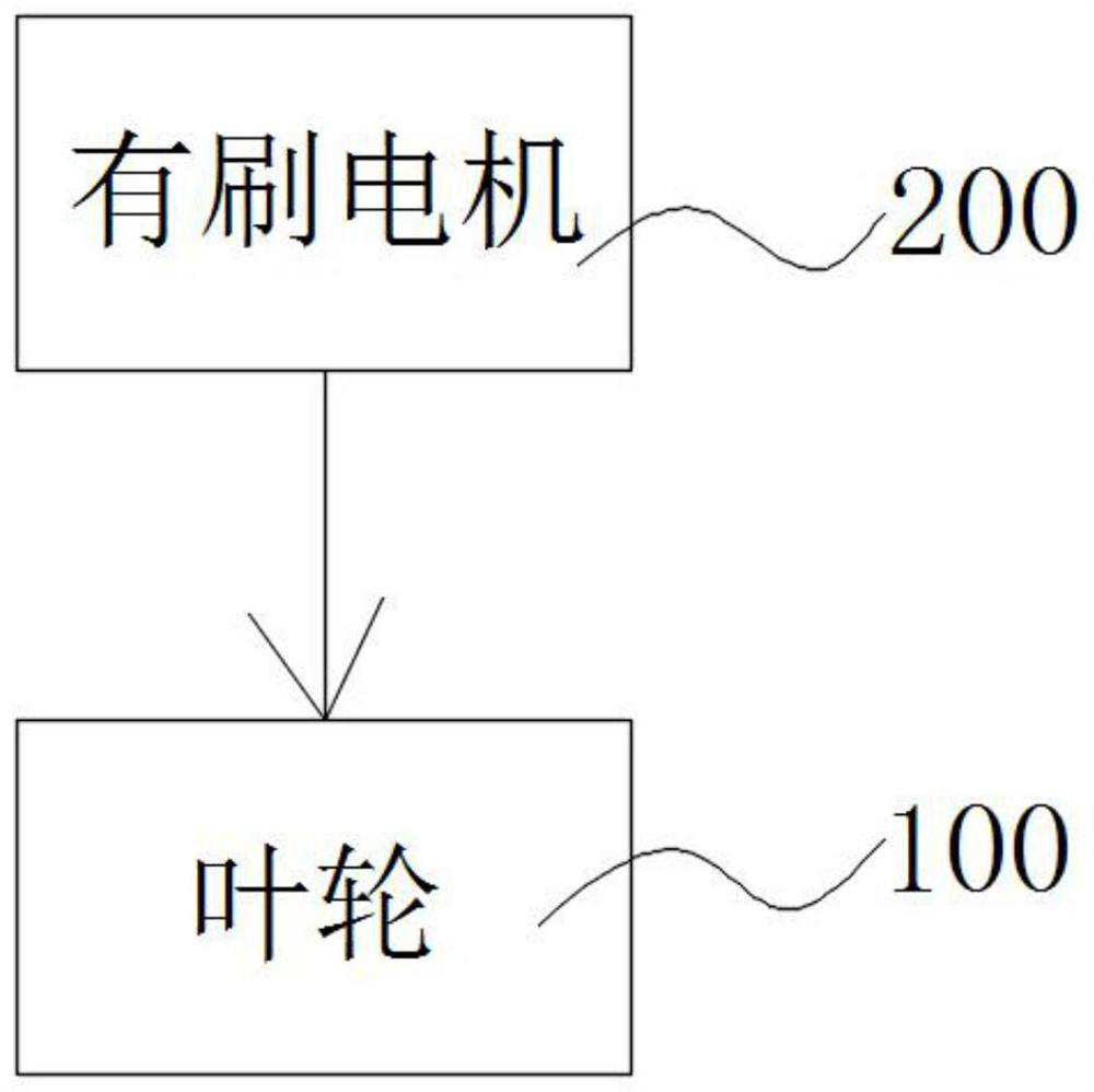
[0026] This program proposes a cooling fan, see figure 1 , the cooling fan includes an impeller 100 and a DC brushed motor 200 that drives the impeller 100 to rotate.

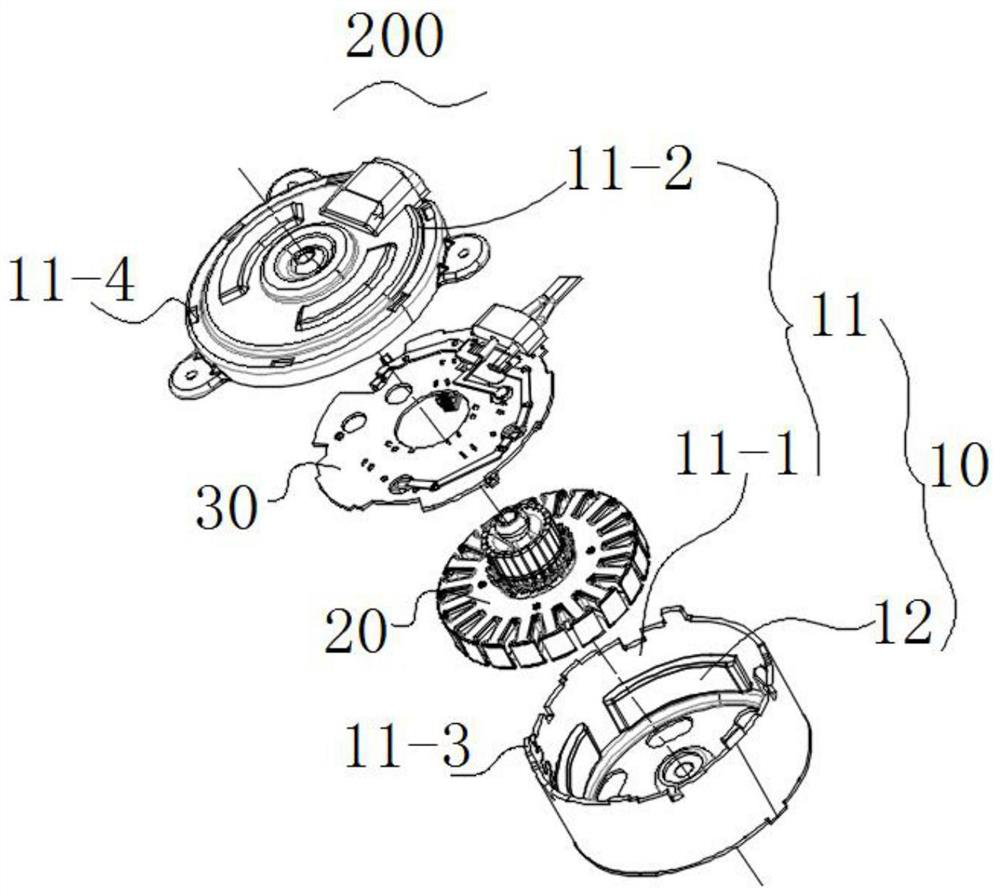
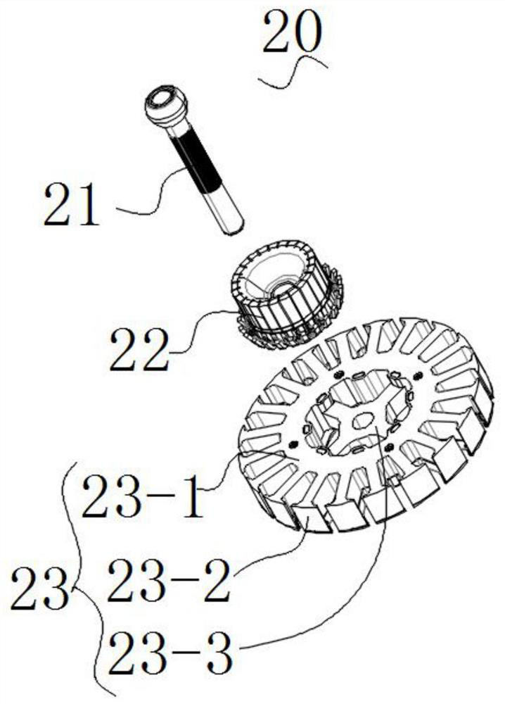
[0027] Among them, see Figure 2-Figure 5 , DC brushed motor 200 includes a stator 10 and a rotor 20 that can rotate relative to the stator 10; wherein the stator 10 includes a housing 11 and 2n pairs of magnetic poles 12 arranged inside the housing 11; the rotor 20 includes a rotating shaft 21, fixed on the rotating shaft The hook commutator 22 on 21 and the magnetizer 23, the winding group (not shown) that is wound in the magnetizer 23 and is electrically connected with the hook of the hook commutator 22 in sequence, and the winding groups communi...


PUM


Abstract

The invention provides a direct-current brush motor and relates to the field of engine cooling fans and the motor comprises a stator, a rotor and an electric brush assembly, the stator comprises a shell and 2n pairs of magnetic poles arranged in the shell, the rotor comprises a rotating shaft, a hook type commutator and a magnetizer which are fixed on the rotating shaft, and a winding group whichis wound in the magnetizer and is electrically connected with a hook of the hook type commutator; and every two hooks arranged on the hook-type commutator at an interval of 180 degrees are electrically connected through a conductor. The electric brush assembly is fixed relative to the shell; the electric brush assembly comprises an insulating plate and n pairs of electric brushes fixed on the insulating plate; every two hooks arranged on the hook type commutator at interval of 180 degrees are electrically connected through the conductor; and compared with the traditional arrangement of n pairsof magnetic poles and n pairs of electric brushes, only n pairs of electric brushes are still needed under the condition that the number of pairs of magnetic poles is increased by 2n pairs, the internal structure of the rotor does not need to be changed, and the use amount of copper wires of a winding group is reduced; high-efficiency output of the whole motor can be realized, and power consumption can be reduced.

Description

technical field [0001] The invention relates to the field of engine cooling fans, in particular to a cooling fan and a DC brushed motor driving the cooling fan. Background technique [0002] Cooling fans are generally used in automobile engines, but due to the compact interior space of automobile engine compartments, the axial length of the cooling fan motor is required to be as short as possible; therefore, due to the limitation of environmental components, the shape of the cooling fan motor is flat. At the same time, considering As far as the internal structure of the brushed motor is concerned, the current common design can only adopt the design method of four (two pairs) brushes, and the four brushes are evenly distributed at 360°. Smooth operation, the number of pairs of magnetic poles set on the stator is the same as the number of pairs of brushes, that is, the same design method of setting four (two pairs) of magnetic poles. [0003] The above design is currently the...

Claims


Application Information

Patent Timeline
Patent Type & Authority Applications(China)
IPC IPC(8): H02K13/04H02K5/14H02K29/00F01P5/04F04D25/08
CPCF01P5/04F01P2005/046F04D25/08H02K5/145H02K13/04H02K29/00
Inventor 汤武陈龙田基
Owner 东风博泽汽车系统有限公司
Why Eureka
Eureka Blog
Learn More