

Vehicle frame
A frame and frame technology, applied to locomotives, bogies, motor vehicles, etc., can solve the problems of reducing the overall fatigue performance of the frame and stress concentration at the joints, so as to avoid the impact of steel impact, improve fatigue life, and improve stress horizontal effect
- Summary
- Abstract
- Description
- Claims
- Application Information
AI Technical Summary
Problems solved by technology
Method used
Image

Examples
Embodiment Construction
[0037] The following will clearly and completely describe the technical solutions in the embodiments of the present invention with reference to the accompanying drawings in the embodiments of the present invention. Obviously, the described embodiments are only some, not all, embodiments of the present invention. Based on the embodiments of the present invention, all other embodiments obtained by persons of ordinary skill in the art without making creative efforts belong to the protection scope of the present invention.
[0038] An embodiment of the invention provides a suspended rail transit system.
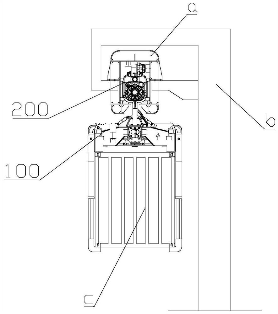
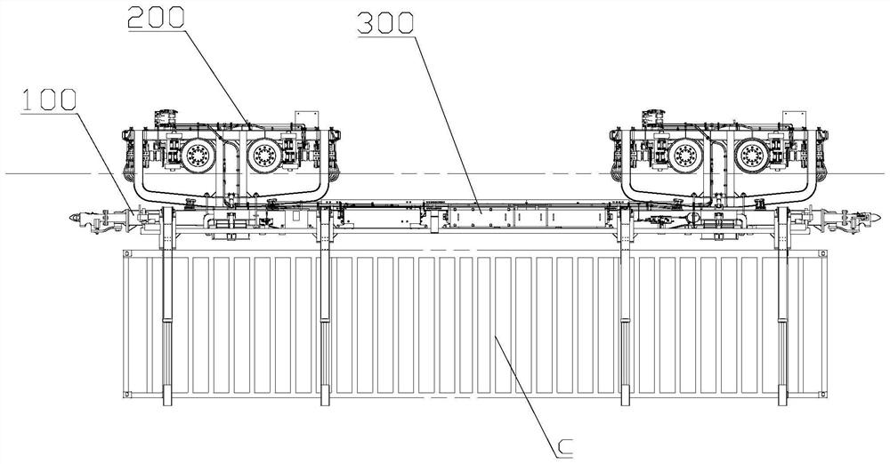
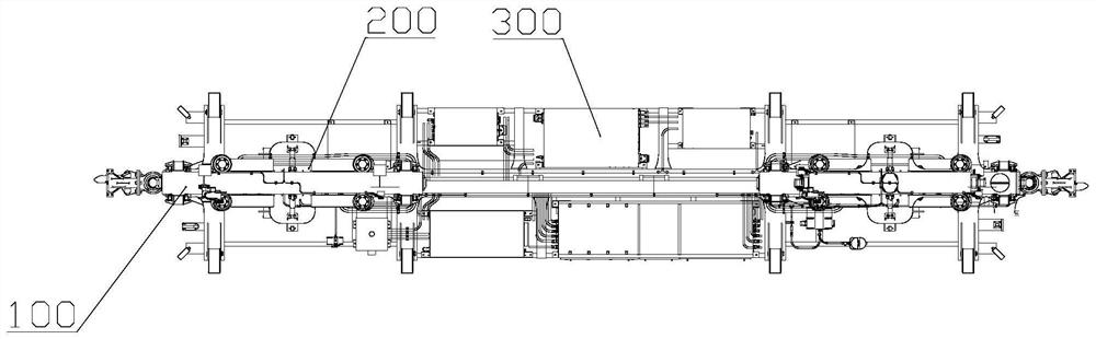
[0039] figure 1 It is a structural schematic diagram of a suspended rail transit system according to an embodiment of the present invention, combined with figure 1 , the system includes a vehicle and a track beam a, the track beam a is supported by a pier b, the vehicle includes a vehicle frame 100 and a plurality of bogies 200, and a plurality of bogies 200 can walk on the trac...
PUM
 Abstract
Description
Claims
Application Information