Eureka AIR delivers breakthrough ideas for toughest innovation challenges, trusted by R&D personnel around the world.

Drilling equipment for geothermal exploration

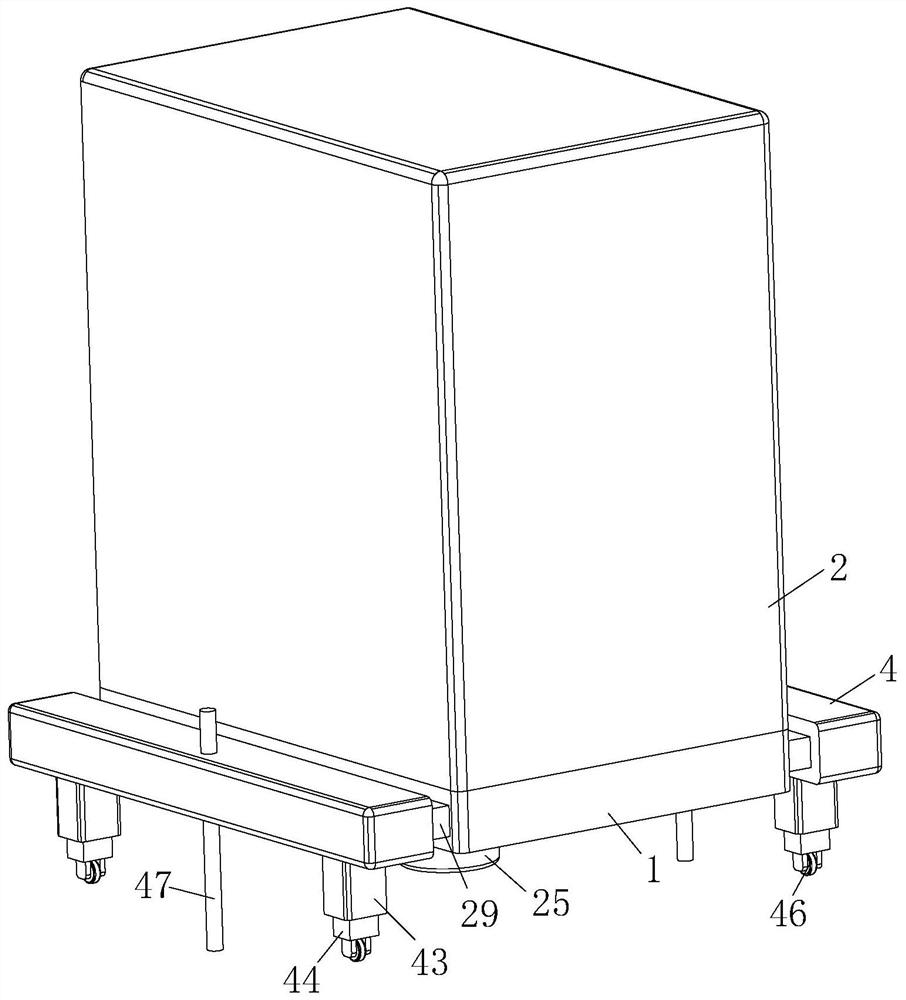
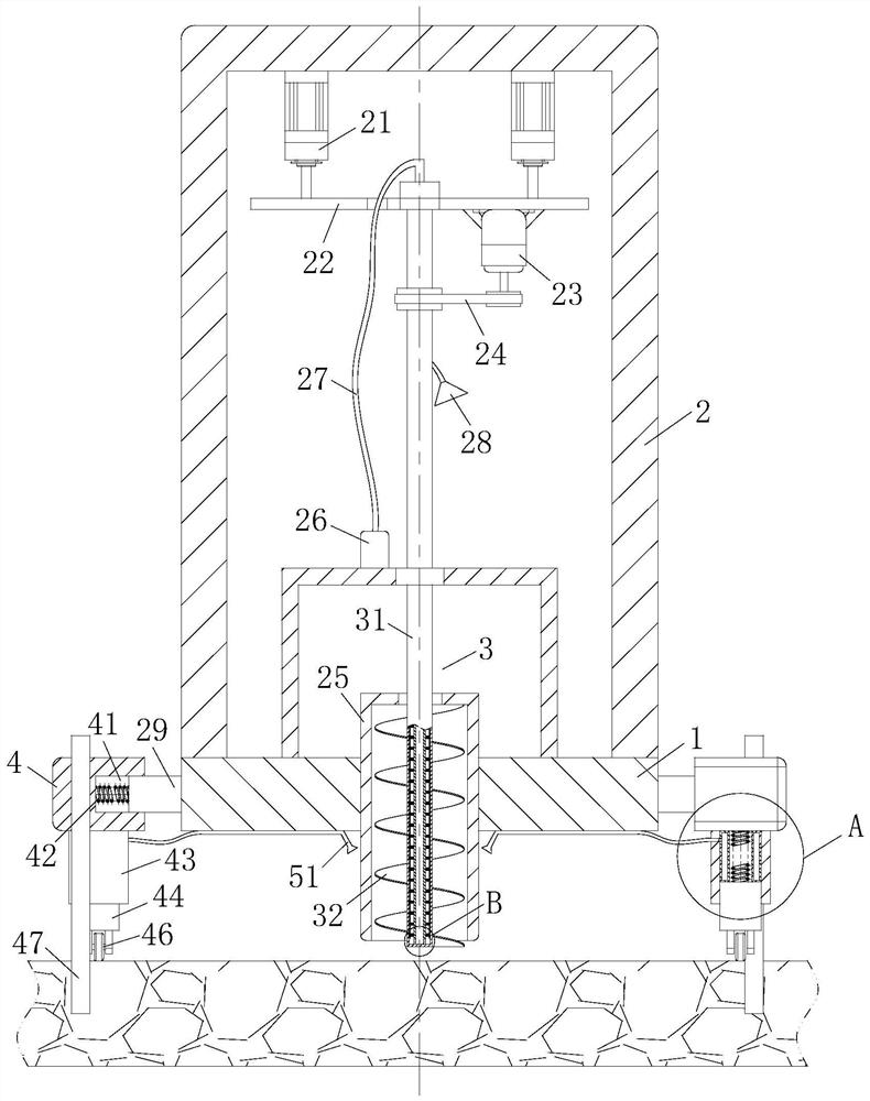
A drilling equipment and geothermal technology, applied in drilling equipment, drilling equipment and methods, mechanical equipment and other directions, can solve the problems of poor cooling effect, scrapped drill bits, affecting the working quality of drill bits, etc., to improve the cooling and cooling effect, improve the use of Longevity, the effect of improving stability and service life

Active Publication Date: 2021-01-29
山东省煤田地质局第一勘探队
View PDF7 Cites 3 Cited by
  • Summary
  • Abstract
  • Description
  • Claims
  • Application Information

AI Technical Summary

Problems solved by technology

[0004] But the drilling equipment in the above-mentioned technology can only effectively buffer in the vertical direction, and the drill bit will also drive the equipment to vibrate in the horizontal direction when it is working, so that the shock absorption effect of the equipment has limitations. The water spray mechanism in the drill can only cool down the top of the drill bit working part, but the drill bit is often at the lowest end of the drill hole when the temperature is relatively high. At this time, only the top of the drill bit working part is not effective in cooling. When encountering metamorphic rock, magmatic rock, such as granite and other hard rock areas, at the same time, it is affected by the geothermal temperature at the bottom of the rock, making it easier for the bottom of the drill bit to generate a large amount of heat during drilling exploration. Cooling treatment will greatly affect the working quality of the drill bit, and even lead to the scrapping of the drill bit

Method used


Image

  • Drilling equipment for geothermal exploration
  • Drilling equipment for geothermal exploration
  • Drilling equipment for geothermal exploration

Examples


Embodiment approach

[0027] As an embodiment of the present invention, a group of uniformly distributed reinforcement blocks 6 are fixedly connected to the side wall of the cooling rod 33 along its axial direction, and water flow channels 61 are opened inside the reinforcement blocks 6; The inside of the rod 31 is set as a hollow structure, so that the strength of the rotating rod 31 becomes lower when it is hit by rocks, so that the rotating rod 31 is prone to deformation or damage after a long time of work. At this time, the cooling rod 33 and the rotating rod During the assembly process of the rod 31, the cooling rod 33 can drive the reinforcing block 6 to be inserted into the inside of the rotating rod 31, and at the same time, by setting the length of the reinforcing block 6, the outer end of the reinforcing block 6 can be attached to the inner wall of the rotating rod 31. When the reinforcement block 6 can play a certain supporting effect on the side wall of the rotating rod 31, the working s...


PUM


Abstract

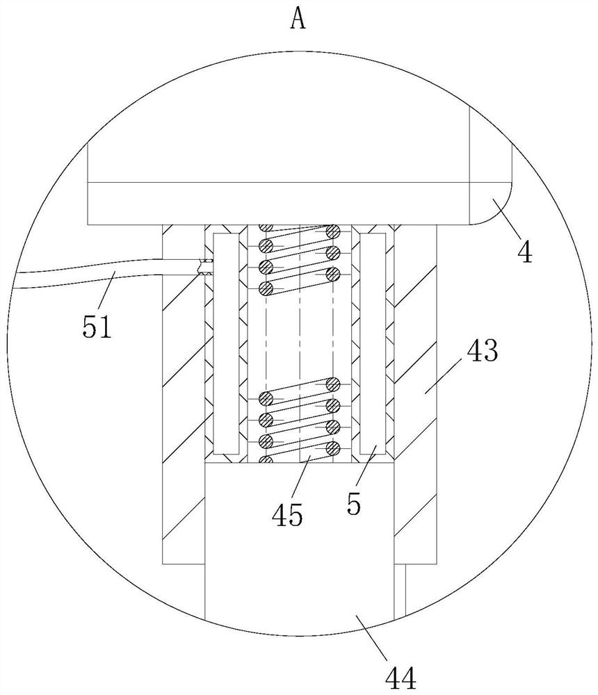
The invention belongs to the technical field of drilling equipment, and particularly relates to drilling equipment for geothermal exploration. The equipment comprises a base and a drilling box; pneumatic push rods are installed in the drilling box, a supporting plate is installed at the bottom ends of the pneumatic push rods, a drill bit is rotatably connected to the middle of the bottom face of the supporting plate, the drill bit is composed of a hollow rotating rod and a cutting part, and a heat dissipation rod is inserted into the rotating rod in a penetrating mode; and sliding plates are connected to the side walls of the base, supporting tables are slidably connected to the outer ends of the sliding plates, sliding cavities are connected to the bottom ends of the supporting tables, and sliding tables are slidably connected into the sliding cavities. According to the drilling equipment, through the arrangement of a damping mechanism and a heat dissipation mechanism, the drilling equipment can conduct damping in all directions; and meanwhile, the equipment can conduct efficient cooling treatment on the drill bit from bottom to top, so that the cooling effect of the drill bit isgreatly improved, and then, the stability and the service life of the drilling equipment working in granite and other hard rock areas are improved and prolonged.

Description

technical field [0001] The invention belongs to the technical field of drilling equipment, in particular to a drilling equipment for geothermal exploration. Background technique [0002] Geological exploration is the work of using technology to dig underground to understand the geological conditions. For places with few ground outcrops, large lithological changes or complex geological structures, the geological conditions cannot be clarified by ground observation alone. Geological exploration engineering is needed to understand and Obtain geological conditions and data in the deep underground. Geothermal exploration is a kind of geological exploration, that is, through various means and methods to explore and detect geothermal heat, determine the appropriate bearing layer, determine the foundation type according to the foundation bearing capacity of the bearing layer, and calculate the investigation and research of foundation parameters Activity. [0003] There are also so...

Claims


Application Information

Patent Timeline
Patent Type & Authority Applications(China)
IPC IPC(8): E21B7/02E21B15/00E21B21/00E21B17/00E21B12/04E21B41/00F16F15/067F16F15/02F16F15/023
CPCE21B7/024E21B15/006E21B15/00E21B21/00E21B17/00E21B12/04E21B41/00F16F15/067F16F15/022F16F15/0237
Inventor 种衍飞秦福锋冯英明臧浩李建郝义
Owner 山东省煤田地质局第一勘探队
Why Eureka
Eureka Blog
Learn More