Reaction kettle control valve capable of realizing automatic flow control through time delay structure

A reaction kettle and control valve technology, applied in the field of control and regulation, can solve problems such as troublesome operation, influence of experimental results, deviation of chemical reagent delivery time, etc., to achieve the effect of accurate reaction results and prevention of failures

Inactive Publication Date: 2021-01-29
夏霆
View PDF0 Cites 0 Cited by
  • Summary
  • Abstract
  • Description
  • Claims
  • Application Information

AI Technical Summary

Problems solved by technology

[0003] When the commonly used control valve controls the injection of chemicals, the staff observes the reaction time of the reaction record, turns the control valve by themselves, and injects the chemical reagents from the delivery tank according to the steps. The deviation of the feeding time will greatly affect the experimental results. Therefore, we propose a reactor control valve with a time-delay structure to automatically control the flow rate.

Method used


Image

  • Reaction kettle control valve capable of realizing automatic flow control through time delay structure
  • Reaction kettle control valve capable of realizing automatic flow control through time delay structure
  • Reaction kettle control valve capable of realizing automatic flow control through time delay structure

Examples


Embodiment Construction

[0021] The following will clearly and completely describe the technical solutions in the embodiments of the present invention with reference to the accompanying drawings in the embodiments of the present invention. Obviously, the described embodiments are only some, not all, embodiments of the present invention. Based on the embodiments of the present invention, all other embodiments obtained by persons of ordinary skill in the art without making creative efforts belong to the protection scope of the present invention.

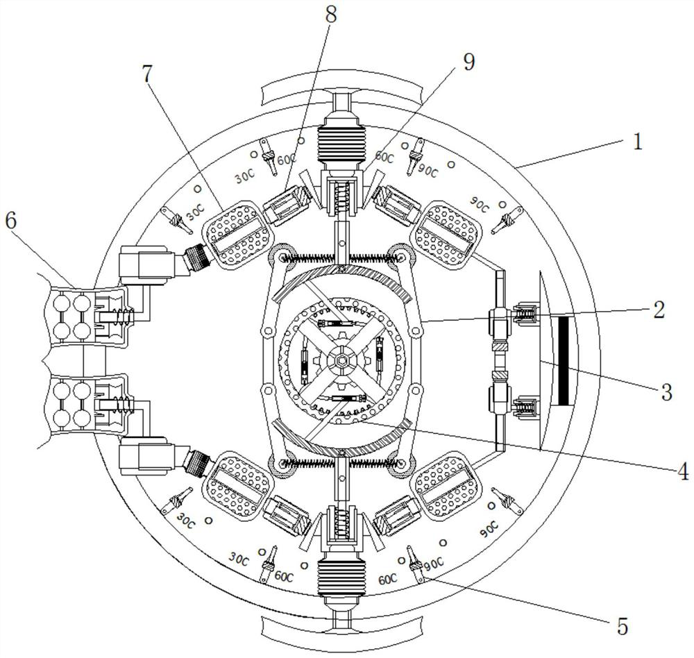
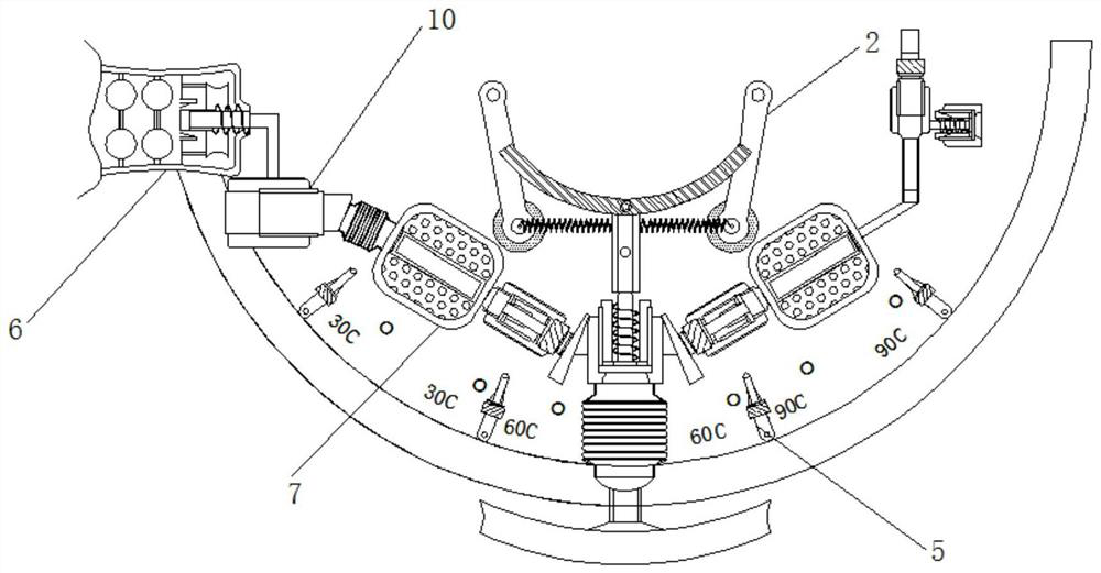
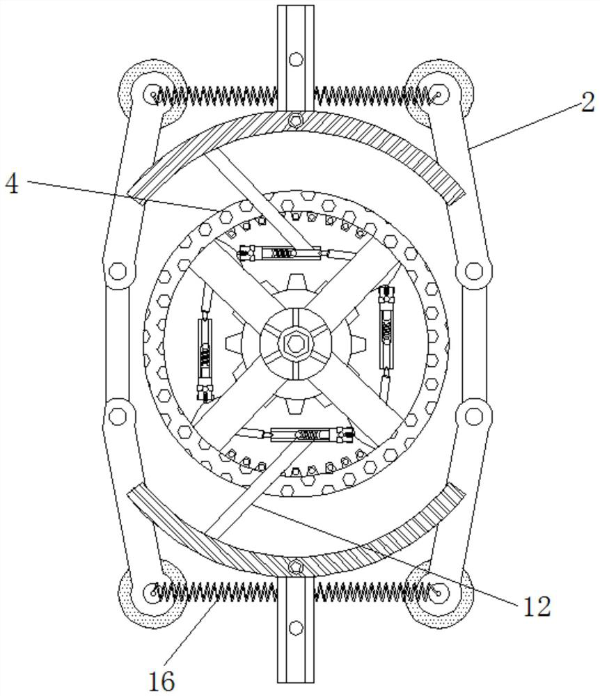
[0022] see Figure 1-6 , a reaction kettle control valve with a delay structure to realize automatic flow control, including a reaction kettle control valve 1, the upper and lower sides of the reaction kettle control valve 1 are fixedly connected with a thermometer 5, and the upper and lower sides of the reaction kettle control valve 1 are fixed. A swing control valve 9 is movably connected through the temperature gauge 5, and the left and right sides of the r...


PUM


Abstract

The invention relates to the technical field of control and regulation, and provides a reaction kettle control valve capable of realizing automatic flow control through a time delay structure. The reaction kettle control valve comprises a reaction kettle control valve body, the upper side and the lower side of the reaction kettle control valve body are fixedly connected with thermometers, the upper side and the lower side of the reaction kettle control valve body are movably connected with swing control valves through the thermometers, and the left side and the right side of the reaction kettle control valve body are movably connected with movable air bags through the swing control valves. According to the reaction kettle control valve capable of realizing automatic flow control through the time delay structure, when a reaction kettle begins to operate, the reaction kettle conducts feeding according to different stages of temperature rising, the temperature rises to 30 DEG C accordingto the principle of thermal expansion and cold contraction, a temperature sensing pipe begins to expand to extrude internal airflow, the airflow pushes a connecting pressing rod to extrude a telescopic spring rod, the airflow enters an air pipe, a movable telescopic frame is pushed through the air pipe, and the movable telescopic frame pushes the swing control valves to be pushed to the 30-degreeareas of the thermometers through inclined blocks.

Description

technical field [0001] The invention relates to the technical field of control and adjustment, in particular to a reactor control valve with a delay structure to realize automatic flow control. Background technique [0002] The broad understanding of the reactor is a container with physical or chemical reactions. Through the structural design and parameter configuration of the container, the heating, evaporation, cooling and low-speed mixing functions required by the process are realized. The control valve is used to regulate and dispense the medicament. [0003] When the commonly used control valve controls the injection of chemicals, the staff observes the reaction time of the reaction record, turns the control valve by themselves, and injects the chemical reagents from the delivery tank according to the steps. The deviation of the feeding time will greatly affect the experimental results. Therefore, we propose a reactor control valve with a time-delay structure to automa...

Claims


Application Information

Patent Timeline
Patent Type & Authority Applications(China)
IPC IPC(8): F16K31/16F16K31/64F16K37/00B01J4/00
CPCB01J4/008F16K31/002F16K31/16F16K37/0016G05D23/01
Inventor 夏霆
Owner 夏霆
Why Eureka
Try Eureka