Flexible printing wiring substrate, electrooptics arrangement, and electronic device

An electro-optical device and wiring substrate technology, which can be applied to printed circuits, printed circuits, nonlinear optics, etc., can solve problems such as hindering the miniaturization of printed substrates, and achieve the effects of simplifying the module process, improving convenience, and suppressing the shrinking of the display area.

Inactive Publication Date: 2003-10-01
BOE TECH GRP CO LTD
View PDF0 Cites 1 Cited by
  • Summary
  • Abstract
  • Description
  • Claims
  • Application Information

AI Technical Summary

Problems solved by technology

In this way, the use of multiple (two in this example) flexible printed wiring boards has become a major factor hindering the miniaturization of the printed circuit board 3

Method used


Image

  • Flexible printing wiring substrate, electrooptics arrangement, and electronic device
  • Flexible printing wiring substrate, electrooptics arrangement, and electronic device
  • Flexible printing wiring substrate, electrooptics arrangement, and electronic device

Examples


Embodiment Construction

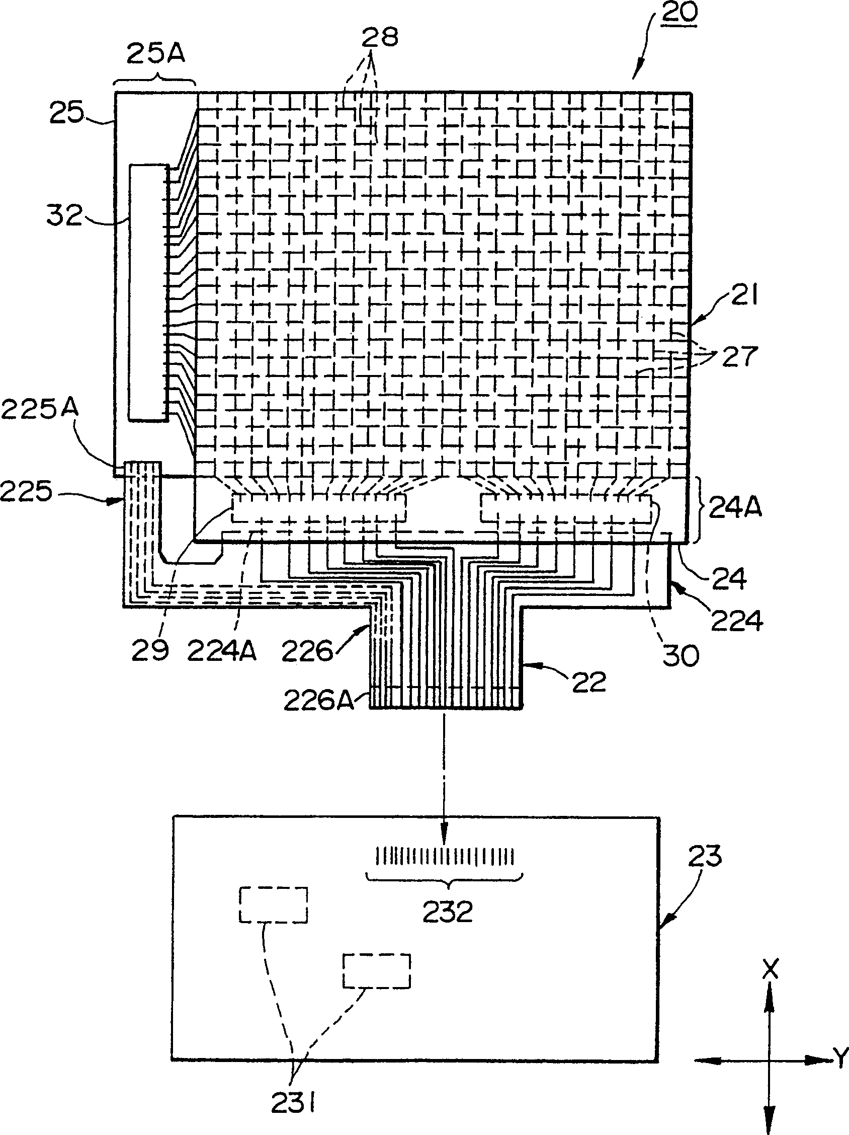
[0083] A liquid crystal device (in this example, a liquid crystal display device), a flexible printed wiring board, and electronic equipment to which the electro-optical device of the present invention is applied will be described in detail below based on the embodiments shown in the drawings. Figure 1-Figure 8 An embodiment in which the present invention is applied to a reflective liquid crystal display device of a passive matrix driving method is shown.

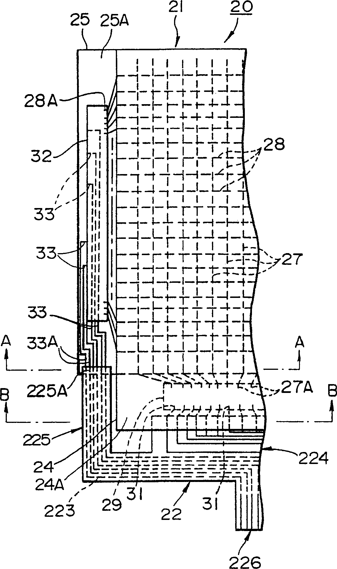
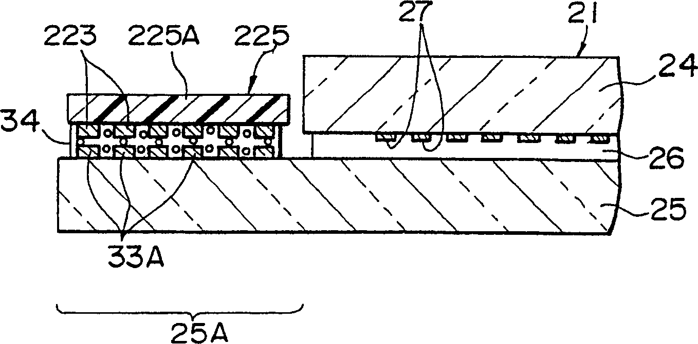
[0084] like figure 1 As shown, the liquid crystal display device 20 of the present embodiment includes: a liquid crystal display panel (electro-optic panel) 21, a flexible printed wiring board 22 that connects a first substrate 24 and a second substrate 25 constituting the liquid crystal display panel 21, and The flexible printed wiring board 22 is connected to a printed board 23 .

[0085] (LCD panel)

[0086] First, the liquid crystal display panel 21 will be described.

[0087] The liquid crystal display panel 21 ha...


PUM


Abstract

Provided is an electro-optical device that simplifies a terminal connection process and can enlarge the area ratio of a display area. The connecting terminal portion connected to the scanning driver IC chip (32) is arranged on the short side portion of the wiring bonding region (25A) of the second substrate (25) in the liquid crystal display panel (21), and the connecting terminal portion and the arrangement The bonding terminal portion on the long side of the wiring bonding region (24A) of the first substrate (24) is bonded to one flexible printed wiring substrate (22) from the same direction.

Description

technical field [0001] The present invention relates to electro-optical devices such as liquid crystal devices, EL (Electroluminescence) electro-optical devices, and the like. The present invention also relates to a flexible printed wiring board used in the electro-optical device and electronic equipment equipped with the electro-optical device. Background technique [0002] In recent years, electro-optical devices have been widely used as portable devices and information display terminals in homes, offices, factories, automobiles, and the like. In particular, liquid crystal display devices have the characteristics of being thin, light in weight, low in voltage, and low in power consumption. Therefore, liquid crystal display devices will exist as the main body of electronic displays now and in the future, and are increasingly widely used in PDAs (Personal Portable Information Terminals) and the like due to low power consumption. [0003] As a conventional liquid crystal di...

Claims


Application Information

Patent Timeline
Patent Type & Authority Patents(China)
IPC IPC(8): H05K1/11H05K3/36
CPCH05K1/118H05K3/361H05K3/363H05K2201/052H05K2201/10136G02F1/13452
Inventor 远藤甲午大石英治有贺泰人
Owner BOE TECH GRP CO LTD
Why Eureka
Try Eureka