
Image processing method and device and electronic system

An image processing and image interpolation technology, applied in the field of image processing, can solve problems such as blurred image edges and inaccurate images

Pending Publication Date: 2021-01-29
MEGVII BEIJINGTECH CO LTD
View PDF0 Cites 2 Cited by
  • Summary
  • Abstract
  • Description
  • Claims
  • Application Information

AI Technical Summary

Problems solved by technology

Generally, the pixels on both sides of the edge of the image have obvious differences. When the interpolation point is on the edge, the pixel value of the interpolation point is usually calculated based on the pixels on both sides of the edge, resulting in blurred edges of the image after interpolation. The problem is likely to cause inaccurate images after special images such as disparity maps and optical flow maps are interpolated by the above method

Method used


Image

  • Image processing method and device and electronic system
  • Image processing method and device and electronic system
  • Image processing method and device and electronic system

Examples


Embodiment 1

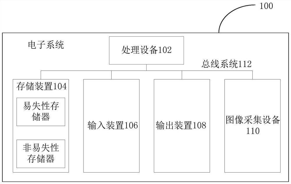
[0040] First, refer to figure 2 An example electronic system 100 for implementing the image processing method, device and electronic system of the embodiments of the present invention will be described.

[0041] like figure 2 A schematic structural diagram of an electronic system is shown, the electronic system 100 includes one or more processing devices 102, one or more storage devices 104, input devices 106, output devices 108, and may also include one or more image acquisition devices 110 , these components are interconnected via bus system 112 and / or other forms of connection mechanisms (not shown). It should be noted that figure 2 The components and structures of the electronic system 100 shown are exemplary rather than limiting, and the electronic system may also have other components and structures as required.

[0042] The processing device 102 may be a gateway, or an intelligent terminal, or a device including a central processing unit (CPU) or other forms of pr...

Embodiment 2

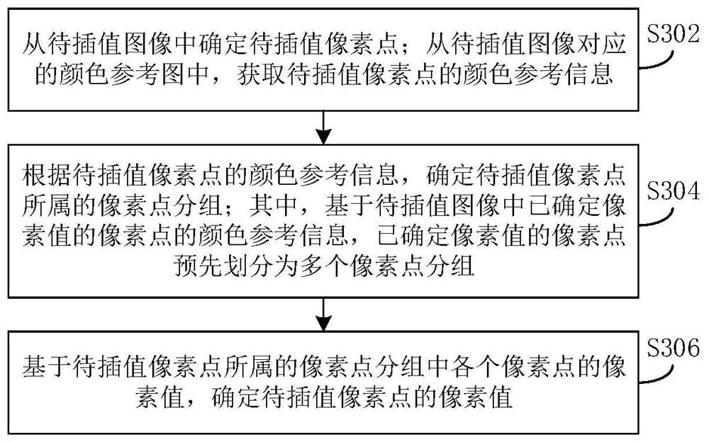
[0049] This embodiment provides an image processing method, such as image 3 As shown, the method includes the following steps:

[0050] Step S302, determining the pixel to be interpolated from the image to be interpolated; obtaining the color reference information of the pixel to be interpolated from the color reference map corresponding to the image to be interpolated;

[0051] The image to be interpolated above can be various types of images, for example, a multi-channel color map, a single-channel or multi-channel depth map, a disparity map, an optical flow map, etc.; the above-mentioned pixel points to be interpolated usually refer to Unknown regions, for example, occluded regions in special images such as disparity maps, optical flow maps, or depth maps, often need to be interpolated, and the occluded regions are usually determined as pixels to be interpolated. The above-mentioned color reference map can be a multi-channel color map, such as a three-channel color map, e...

Embodiment 3

[0061] This embodiment provides another image processing method, which is implemented on the basis of the foregoing embodiments. Among the above multiple pixel point groups, each pixel point group corresponds to a pixel feature; different pixel point groups correspond to different pixel features.

[0062] The above pixel features can be determined according to the color reference information of each pixel point; the color reference information of each pixel point has a certain difference, so different pixel point groups correspond to different pixel features.

[0063] This embodiment focuses on the specific implementation process of the step of determining the pixel group to which the pixel to be interpolated belongs according to the color reference information of the pixel to be interpolated (realized through steps S404-S406), as shown in Figure 4 As shown, the method includes the following steps:

[0064] Step S402, determining the pixel to be interpolated from the image t...


PUM


Abstract

The invention provides an image processing method and device and an electronic system. The method comprises the steps of determining to-be-interpolated pixel points from a to-be-interpolated image; obtaining color reference information of the pixel points to be interpolated from a color reference image corresponding to the to-be-interpolated image; determining a pixel point group to which the to-be-interpolated pixel point belongs according to the color reference information of the to-be-interpolated pixel point; and determining the pixel value of the to-be-interpolated pixel point based on the pixel value of each pixel point in the pixel point group to which the to-be-interpolated pixel point belongs. In the mode, the pixel point group is determined by using the color reference information of the to-be-interpolated, and then the pixel value of the to-be-interpolated pixel point is determined based on the pixel value of the pixel point in the group, so that the pixel value of the to-be-interpolated pixel point is determined because the color reference information of the pixel points in the same group is similar. Use of pixel points with large color difference on two sides of the edge for interpolation calculation can be avoided, and the accuracy of the interpolated image is improved for special images such as a disparity map and an optical flow graph.

Description

technical field [0001] The present invention relates to the technical field of image processing, in particular to an image processing method, device and electronic system. Background technique [0002] Image interpolation is the use of pixels with known pixel values ​​on the image to calculate the pixel values ​​of unknown pixel values. Pixels with unknown pixel values ​​are also called interpolation points. In related technologies, the pixel value of the interpolation point is usually calculated according to the pixel values ​​of the surrounding pixel points, such as nearest neighbor interpolation algorithm, bilinear interpolation algorithm, cubic polynomial interpolation algorithm and so on. Generally, the pixels on both sides of the edge of the image have obvious differences. When the interpolation point is on the edge, the pixel value of the interpolation point is usually calculated based on the pixels on both sides of the edge, resulting in blurred edges of the image af...

Claims


Application Information

Patent Timeline
IPC IPC(8): G06T3/40
CPCG06T3/4007G06T3/4023
Inventor 郑子华
Owner MEGVII BEIJINGTECH CO LTD
Learn More