Heat dissipation structure of an energy storage battery box

A technology of heat dissipation structure and energy storage battery, which is applied to structural parts, secondary batteries, battery pack components, etc., can solve the problems of large temperature difference of battery cells, large temperature difference of battery box, affecting battery performance and life, etc. , to achieve the effect of enhancing the base structure of the battery cell, improving the efficiency of heat dissipation and ventilation, and improving the efficiency of ventilation and heat dissipation.

Active Publication Date: 2021-08-31
SHANGHAI YUYUAN POWER TECH CO LTD
View PDF7 Cites 0 Cited by
  • Summary
  • Abstract
  • Description
  • Claims
  • Application Information

AI Technical Summary

Problems solved by technology

Generally, the number of batteries inside the energy storage power station is huge and the arrangement is tight, which causes the batteries to generate a lot of heat during operation and is not easy to discharge, resulting in a large temperature difference between the inside and outside of the battery box, and the temperature difference of the cells at different positions in the battery box Larger, these differences will affect the capacitance and internal resistance of the battery, resulting in unstable factors, greatly affecting the performance and life of the battery
[0003] The existing design of the battery box has taken into account that the cold air from the air conditioner is sent into the battery box, and then the fan is used to force the heat exchange and cooling of the battery box. Circulation, resulting in energy loss and low cooling efficiency, it is more likely to exacerbate the temperature difference of the battery core, causing adverse effects and reducing the service life of the battery

Method used


Image

  • Heat dissipation structure of an energy storage battery box
  • Heat dissipation structure of an energy storage battery box
  • Heat dissipation structure of an energy storage battery box

Examples


Embodiment

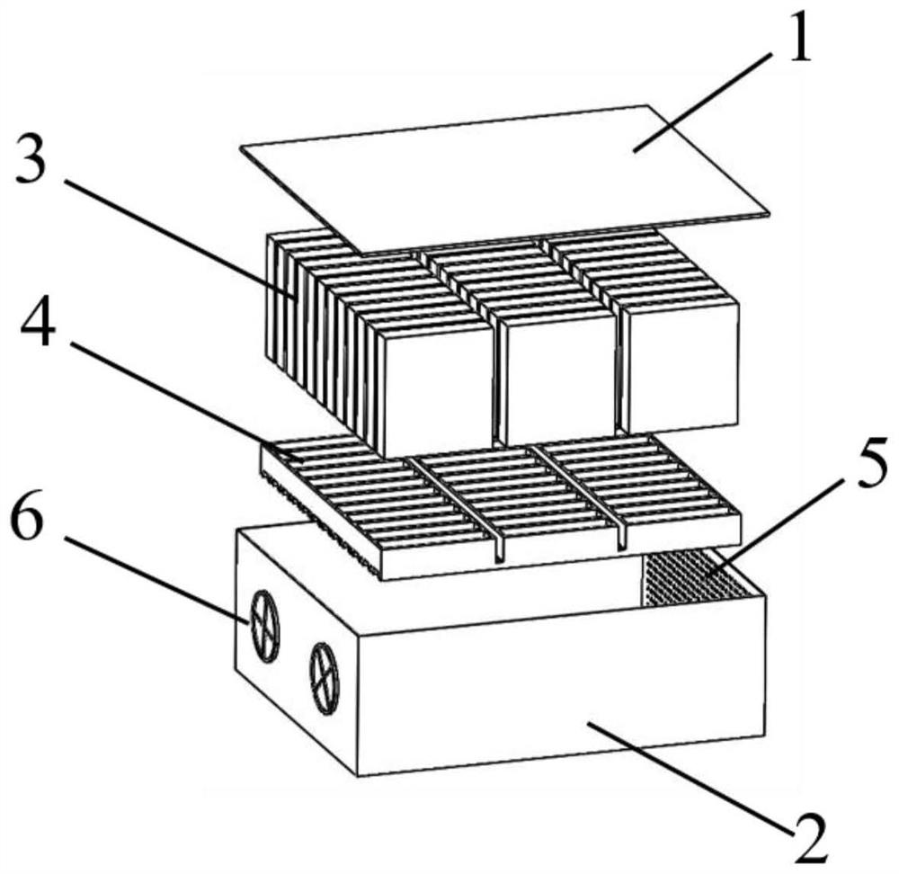
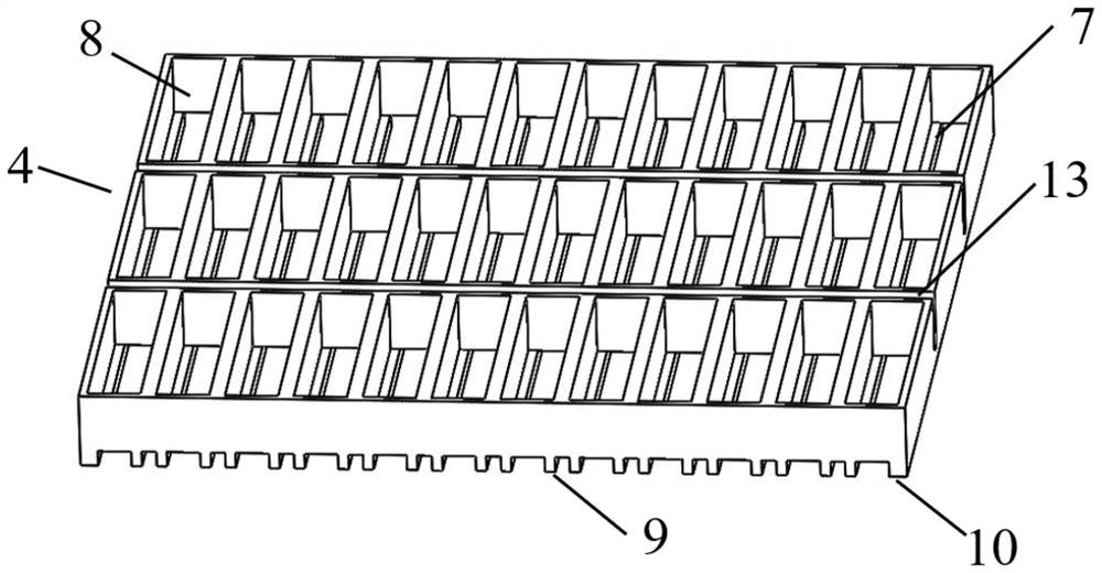
[0048] Such as Figure 1-8 , 10. In a preferred embodiment, a heat dissipation structure of an energy storage battery box includes an upper cover 1 , a casing 2 , a battery cell 3 and a battery cell base 4 located below the battery cell 3 .

[0049] The shell 2 is a hollow cuboid structure with an open upper end, and the size of the shell 2 is 454mm×420mm×173mm;

[0050] The size of the upper cover 1 is the same as the size of the bottom surface of the shell 2, and the upper cover 1 is connected to the shell 2 in a detachable manner;

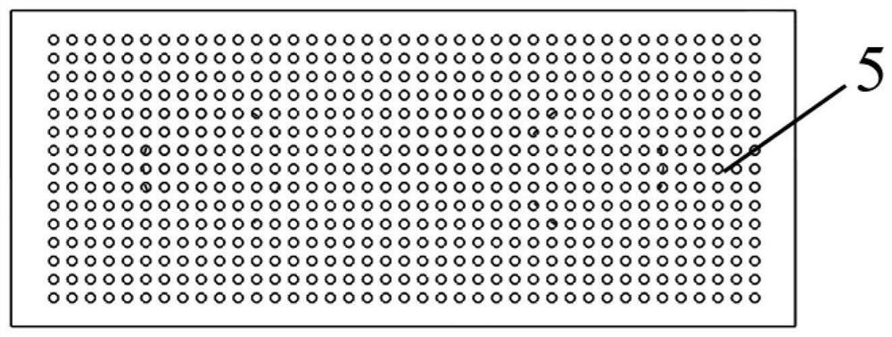
[0051] Two fans 6 are installed on one of the sides of the housing 2, and the other side facing the side is an air inlet 5, and the air inlet 5 is composed of a plurality of densely arranged round holes;

[0052] The fan 6 is used to provide power, and the heat exchanged hot air inside the traction battery box is discharged out of the battery box;

[0053] The air inlet 5 is connected with the air outlet of the air conditioner;

[0054] The bat...


PUM

PropertyMeasurementUnit
heightaaaaaaaaaa
widthaaaaaaaaaa
widthaaaaaaaaaa

Abstract

The invention provides a heat dissipation structure of an energy storage battery box, which relates to the field of energy storage battery boxes, including an upper cover, a casing, a battery cell and a battery cell base located below the battery cell, and two fans are installed on one side of the casing. The other side directly opposite to this side is the air inlet. The cell base consists of upper and lower parts. The upper part is composed of several rows of battery slots that penetrate up and down. The lower part is composed of several parallel narrow beams with rectangular cross-sections. Composition, the narrow beams include multiple internal beams and two external beams, the two narrow beams on the lower part of the two side walls of each cell slot form two bosses, and the adjacent two narrow beams form a ventilation duct under the cell . In the present invention, the airflow enters the battery box through the air inlet on the side of the battery box shell, and through the traction force of the fan, the airflow can flow through the upper part, both sides and the bottom of the battery cell, and the heat generated by the battery cell is taken out of the battery box, greatly improving ventilation and heat dissipation efficiency.

Description

technical field [0001] The invention belongs to the field of energy storage battery boxes, and in particular relates to a heat dissipation structure of an energy storage battery box. Background technique [0002] With the continuous maturity of renewable energy technologies such as solar power generation technology and wind power generation technology, electric energy storage equipment is changing with each passing day. In order to achieve peak load shaving and valley filling, cooperate with compensation, reduce load peaks, fill load valleys, and reduce power grid load peaks and valleys. To balance power generation and electricity consumption, the energy storage power station converts the electrical energy output by the power generation system into chemical energy and stores it for use when the power supply is insufficient. The core of the energy storage power station is the energy storage battery. Generally, the number of batteries inside the energy storage power station i...

Claims


Application Information

Patent Timeline
Patent Type & Authority Patents(China)
IPC IPC(8): H01M10/613H01M10/627H01M10/647H01M10/6556H01M10/6563H01M50/103
CPCH01M10/613H01M10/627H01M10/647H01M10/6556H01M10/6563Y02E60/10
Inventor 尚德华刘越
Owner SHANGHAI YUYUAN POWER TECH CO LTD
Why Eureka
Try Eureka