Torsion wire loosening device for communication cable stripping machine

A communication cable and peeling machine technology, which is applied to electromechanical devices, equipment for dismantling/armoring cables, electrical components, etc., can solve the problems of difficult peeling of the protective layer, and achieve the effect of good separation effect and improved peeling efficiency.

Active Publication Date: 2021-01-29
深圳市奥进电子科技有限公司
View PDF7 Cites 3 Cited by
  • Summary
  • Abstract
  • Description
  • Claims
  • Application Information

AI Technical Summary

Problems solved by technology

[0005] The purpose of the present invention is to provide a torsion loosening device for a communication cable stripping machine that facilitates the separation of the protective layer and the cable core for the problem that the protective layer is easily attached to the cable core and is difficult to peel off.

Method used


Image

  • Torsion wire loosening device for communication cable stripping machine
  • Torsion wire loosening device for communication cable stripping machine
  • Torsion wire loosening device for communication cable stripping machine

Examples


Embodiment 1

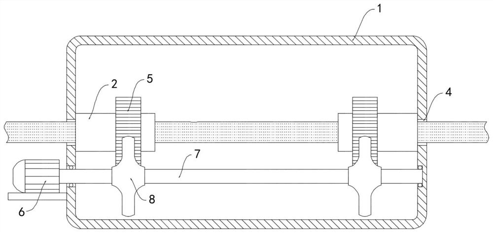
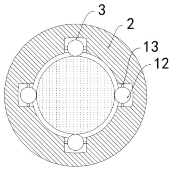
[0019] like Figure 1-3 As shown, a twisting and loosening device for a communication cable stripping machine includes a housing 1, and a rotating drum 2 is rotatably connected to the inner walls on both sides of the housing 1, and the rotating drum 2 is provided with a wire that only allows the communication cable to move along its axis. To the limit mechanism 3 that slides, the limit mechanism 3 includes grooves that are distributed on the inner side wall of the drum 2 in an annular array, and balls 12 are arranged in the grooves, and the balls 12 pass through the limit rotating rod 13 and the side wall of the groove. Rotationally connected, the limit rotating rod 13 only allows the ball 12 to rotate toward the axis of the drum 2 , and the side wall of the housing 1 is provided with a threading hole 4 corresponding to the drum 2 .

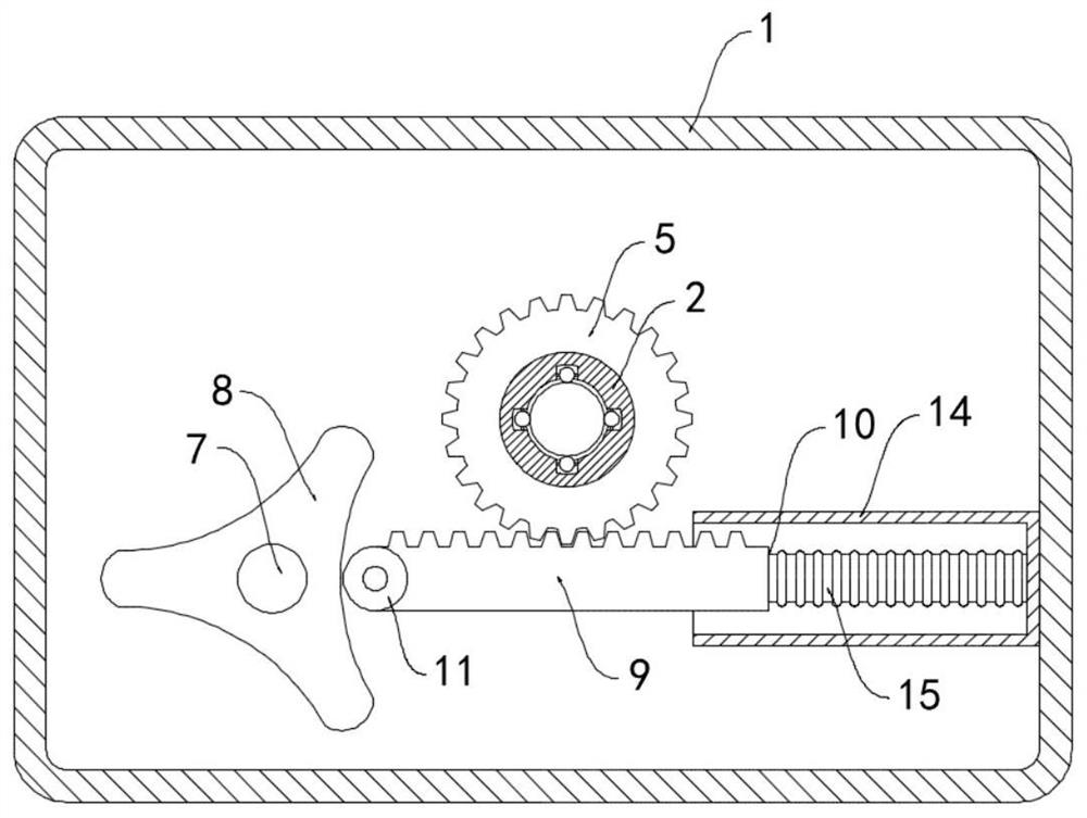
[0020] A gear 5 is coaxially and fixedly sleeved outside the drum 2, a motor 6 is installed on the side wall of the housing 1, and a rotating sh...

Embodiment 2

[0023] like Figure 4 As shown, the difference between this embodiment and Embodiment 1 is that: the inner top surface and the inner bottom surface of the housing 1 are fixedly connected with the mounting seat 16, and the mounting seat 16 is provided with a plurality of equidistantly arranged chute 17 , the slide groove 17 is sealed and slidably connected with a slider 18, the slider 18 is fixedly connected with a push rod 19, the push rod 19 located on the inner top surface of the housing 1 and the push rod 19 located on the inner bottom surface of the housing 1 are alternately arranged, the sliding The slots 17 communicate with the elastic airbag 15 through the air duct 20 .

[0024] In this embodiment, when the rack 9 reciprocates in the horizontal direction, it repeatedly squeezes and stretches the elastic airbag 15. When the elastic airbag 15 is compressed, the gas in the elastic airbag 15 is squeezed into the chute 17, and the chute The air pressure in 17 increases, and...


PUM


Abstract

The invention belongs to the technical field of communication cables, and particularly relates to a torsion wire loosening device for a communication cable stripping machine, which comprises a shell,the inner side walls of the two sides of the shell are rotatably connected with rotary drums, and the rotary drums are internally provided with limiting mechanisms which only allow the communication cables to slide in the axial directions of the rotary drums. A threading hole corresponding to the rotary drum is formed in the side wall of the shell, the rotary drum is coaxially and fixedly sleevedwith a gear, a motor is installed on the side wall of the shell, a rotary shaft is coaxially and fixedly connected to an output shaft of the motor, and the other end of the rotary shaft penetrates through the side wall of the shell and is rotationally connected with the inner side wall of the other side of the shell; and two disc-shaped cams are fixedly connected outside the rotating shaft in a sleeving mode, two horizontal racks are arranged in the shell, the racks are meshed with the gear, and one end of each rack is connected with the inner side wall of the shell through a reset mechanism.By repeatedly twisting and extruding the communication cable, the separation and dislocation of the protective layer and the cable core are promoted, and the communication cable is convenient to peel.

Description

technical field [0001] The invention belongs to the technical field of communication cables, in particular to a twisting loosening device for a communication cable stripping machine. Background technique [0002] The communication cable is composed of a cable core and a protective layer. The cable core is the main part of information transmission. At the same time, in order to protect the cable core from moisture, external mechanical damage and electrical interference, a protective layer needs to be added outside the cable core. , Communication cables are widely used in people's lives and production processes. When recycling old cables, the protective layer outside the cable core needs to be stripped and classified. [0003] In the prior art, a stripping machine is usually used when stripping communication cables, and most traditional communication cable stripping machines directly cut the communication cable skin by cutting blades for stripping treatment. However, due to th...

Claims


Application Information

Patent Timeline
Patent Type & Authority Applications(China)
IPC IPC(8): H02G1/12H02K7/06
CPCH02G1/12H02K7/06
Inventor 钟雅婷
Owner 深圳市奥进电子科技有限公司
Why Eureka
Try Eureka