Underwater acoustic wireless networking method and device based on DTN architecture
A wireless networking and underwater acoustic technology, applied in wireless communication, network planning, ultrasonic/sonic/infrasonic transmission systems, etc., to achieve high data transmission efficiency and good compatibility
- Summary
- Abstract
- Description
- Claims
- Application Information
AI Technical Summary
Problems solved by technology
Method used
Image

Examples
Embodiment 1
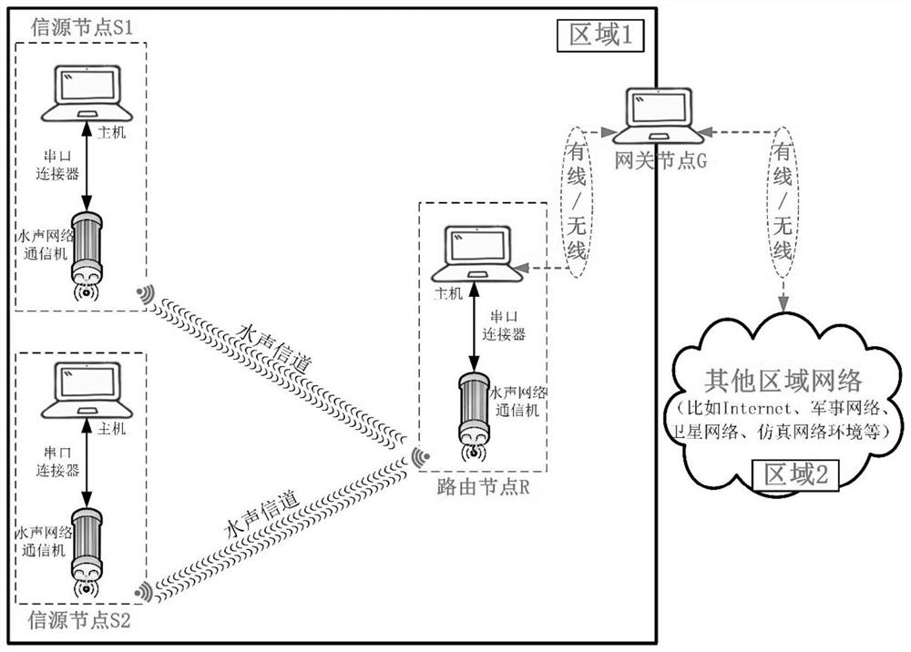
[0091] Such as image 3 As shown, the specific process of data interaction between different nodes is as follows:
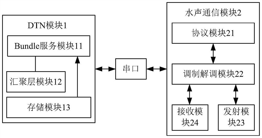
[0092] The routing node R in a certain logical area in the DTN network is in the monitoring state, waiting for the automatic access of the source node S1 and S2 for data transmission, when the Bundle service of the source node S1 or S2 for data transmission When the module 11 has a Bundle message packet to send, the serial port aggregation layer module 12 first generates a control packet with the ID number of the local routing node and sends it to the underwater acoustic communication module 2 through the serial port, and the protocol module 21 in the underwater acoustic communication module 2 controls the The packet is encapsulated into an underwater acoustic protocol data packet, and then coded and modulated by the modulation and demodulation module 22, and finally transmitted to the underwater acoustic channel by the transmitting module 23, and the receiving m...
Embodiment 2
[0094] Such as Figure 4 As shown, in the underwater acoustic wireless local area network, when the source node S1 sending data and the routing node R receiving data are communicating on the link established successfully, if the source node S2 sending data passes through Sending a control packet to initiate the link establishment process with the routing node R will interrupt the communication link between the source node S1 and the routing node R, and then the source node S1 needs to compete for access to the routing node R again.
PUM
 Abstract
Description
Claims
Application Information
PatSnap Eureka turns technology decisions into work you can execute. Powered by our Innovation Knowledge Graph, it runs expert workflows across engineering, life sciences, materials and intellectual property. Get your review-ready output in minutes.


