A voltage sag monitoring device

A technology for monitoring devices and voltage sags, which is applied to the installation of clamping/extracting devices, electrical components, and support structures, etc., and can solve problems such as inconvenient installation and replacement of circuit boards, poor cooling effect of monitoring devices, and easy damage to electronic components , to achieve the effect of improving monitoring work efficiency, improving heat dissipation effect, and reducing maintenance difficulty

Active Publication Date: 2022-04-22
南京巴斯勒自动化设备有限公司
View PDF27 Cites 0 Cited by
  • Summary
  • Abstract
  • Description
  • Claims
  • Application Information

AI Technical Summary

Problems solved by technology

[0004] The purpose of the present invention is to provide a voltage sag monitoring device, which can quickly install the circuit board, reduce the difficulty of maintenance, and can effectively improve the heat dissipation effect, prevent overheating and damage of electronic components, and thus improve the monitoring work efficiency. It solves the problem that the currently used voltage sag monitoring device is poor in safety and stability, it is not convenient to install and replace the circuit board, and the heat dissipation effect of the monitoring device is poor, and the electronic components are prone to damage due to overheating, which will cause the voltage sag monitoring device The problem of reduced work efficiency

Method used


Image

  • A voltage sag monitoring device
  • A voltage sag monitoring device
  • A voltage sag monitoring device

Examples


Embodiment Construction

[0024] The technical solutions in the embodiments of the present invention will be clearly and completely described below with reference to the accompanying drawings in the embodiments of the present invention. Obviously, the described embodiments are only a part of the embodiments of the present invention, but not all of the embodiments. Based on the embodiments of the present invention, all other embodiments obtained by those of ordinary skill in the art without creative efforts shall fall within the protection scope of the present invention.

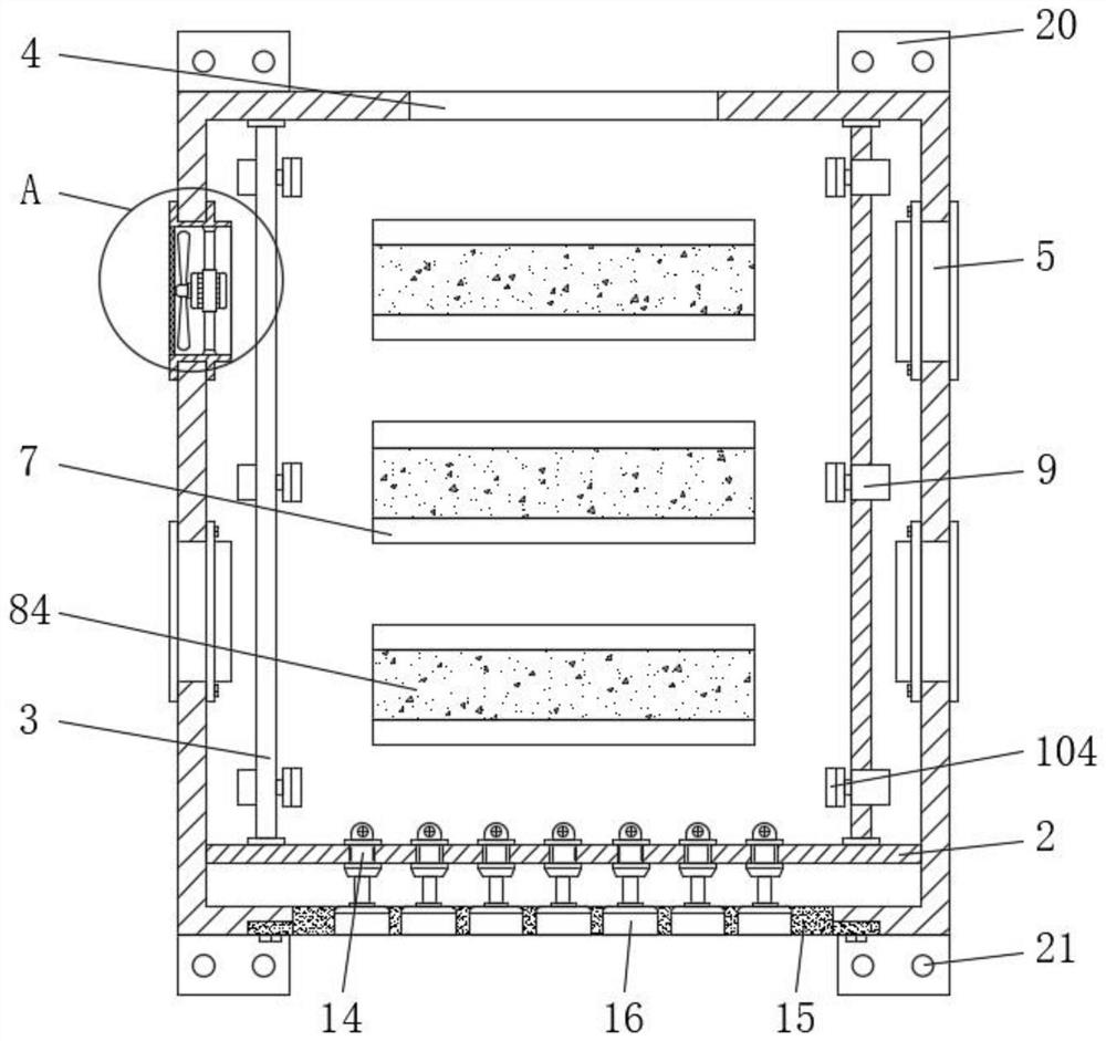
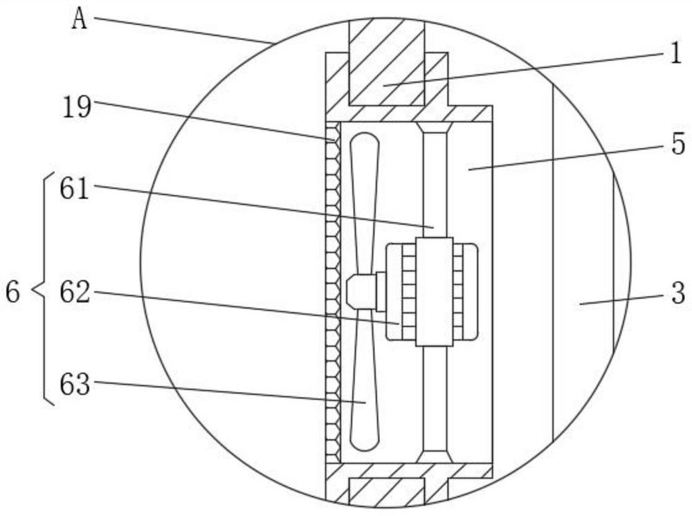
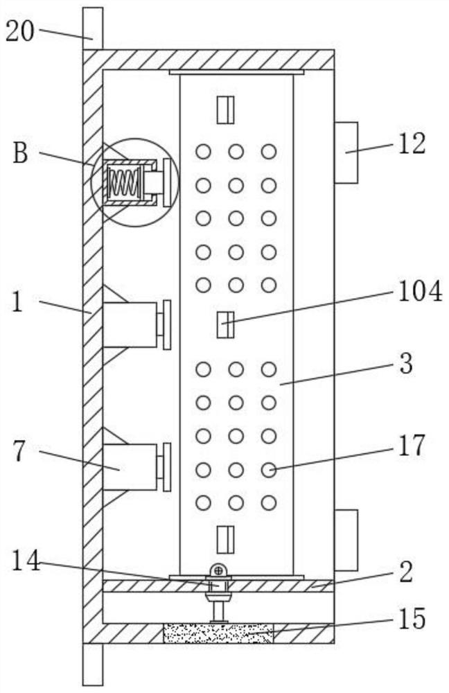
[0025] see Figure 1-6 , a voltage sag monitoring device, comprising a shell 1, the inner cavity of the shell 1 is bolted with a support plate 2, the left and right sides of the top of the support plate 2 are bolted with baffles 3, and the top of the baffle 3 is connected to the The inner wall of the casing 1 is bolted, the top of the casing 1 is provided with a ventilation groove 4, and the left and right sides of the casing 1 are em...


PUM


Abstract

The present invention relates to the technical field of electric equipment, in particular to a voltage sag monitoring device, comprising a housing, the inner cavity of the housing is bolted with a support plate, and the left and right sides of the top of the support plate are bolted with baffles , and the top of the baffle is bolted to the inner wall of the housing, the top of the housing is provided with ventilation slots, the left and right sides of the housing are embedded with installation frames, and the installation frame and the inner cavity of the housing Connectivity; the invention has the advantages of being able to quickly install the circuit board, reducing the difficulty of maintenance, effectively improving the heat dissipation effect, preventing overheating and damage to electronic components, and improving the monitoring work efficiency. The safety and stability are poor, it is not convenient to install and replace the circuit board, and the heat dissipation effect of the monitoring device is poor, and the electronic components are prone to damage due to overheating, which will lead to the problem of reduced working efficiency of the voltage sag monitoring device.

Description

technical field [0001] The invention relates to the technical field of power equipment, in particular to a voltage sag monitoring device. Background technique [0002] With the development of power electronic devices, especially the continuous increase of sensitive loads such as computer equipment, microelectronic equipment and power electronic equipment, the requirements of power users on the power supply quality of power distribution systems are increasing. Voltage sag refers to an event in which the rms value of the supply voltage drops suddenly in a short period of time. The Institute of Electrical and Electronics Engineers defines it as the drop in the rms value of the voltage to within the range of 90% to 10% of the rated value, and the duration is 0.5 to 30 cycles, in which the ratio of the voltage rms value at the time of sag to the rated voltage rms value is defined as the sag amplitude, and the time between the occurrence and the end of the sag is defined as the du...

Claims


Application Information

Patent Timeline
Patent Type & Authority Patents(China)
IPC IPC(8): H05K7/14H05K7/20H05K5/02
CPCH05K7/1401H05K7/20172H05K7/20181H05K5/0213H05K5/03
Inventor 常虎刘磊
Owner 南京巴斯勒自动化设备有限公司
Why Eureka
Try Eureka