Bidirectional adjustable elastic intramedullary nail
An intramedullary nail and adjustable technology, applied in the field of two-way adjustable elastic intramedullary nails, can solve the problems of stress stimulation at the fracture end, slow bone mineralization speed, and long internal fixation time, so as to accelerate fracture healing and avoid stress shielding , a wide range of effects
- Summary
- Abstract
- Description
- Claims
- Application Information
AI Technical Summary
Problems solved by technology
Method used
Image
Examples
Embodiment 1
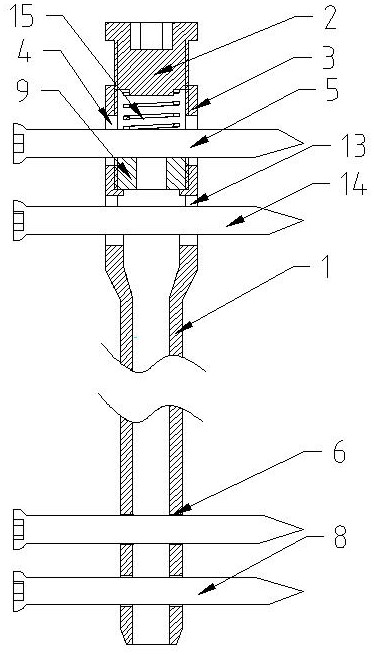
[0037] Embodiment one, such as figure 1 As shown, a two-way adjustable elastic intramedullary nail includes a main intramedullary nail, the main nail of the intramedullary nail is a hollow structure, and the main nail of the intramedullary nail includes a proximal end 3 of the intramedullary nail, an 1. The proximal end 3 of the intramedullary nail and the main body 1 of the intramedullary nail are integrally structured, the diameter of the proximal end 3 of the intramedullary nail is larger than the diameter of the main body 1 of the intramedullary nail, and two A through power screw hole, a power bone screw is installed in the power screw hole, and the power bone screw can move axially along the power screw hole, and an upper power screw hole 4 and a lower power screw hole 13 are installed respectively. The bone screw 5 and the lower dynamic bone screw 14 are provided with two penetrating static screw holes 6 on the main body 1 of the intramedullary nail away from the proxim...
Embodiment 2
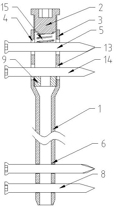
[0040] Embodiment two, such as figure 2 As shown, the difference from Embodiment 1 is that an absorbable washer 9 is provided under the lower dynamic bone screw 14, and the absorbable washer 9 is supported by the proximal end 3 of the intramedullary nail and the gradient part of the main body 1 of the intramedullary nail. The absorbable washer 9 The upper part supports the lower dynamic bone screw 14. Screw in the tail cap 2 to give the downward axial stress of the pressure regulating spring 15, and then give the upper dynamic bone screw 5 a downward axial stress, and the bone fixed on the proximal end 3 of the intramedullary nail is downwardly pressed by the pressure regulating spring 15. Axial stress, and then give the upper dynamic bone screw 5, the pressure regulating spring 15, the end cap 2, the proximal end of the intramedullary nail 3, the main body of the intramedullary nail 1, the upper static bone screw and the lower static bone screw 8 at the distal end An upward...
Embodiment 3
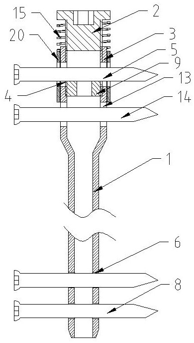
[0041] Embodiment three, such as image 3 As shown, the difference from Embodiment 1 is that an absorbable washer 9 is provided above the upper dynamic bone screw 5 , the upper dynamic bone screw 5 supports the absorbable washer 9 , and the upper part of the absorbable washer 9 touches the tail cap 2 . The outer side of the proximal end 3 of the intramedullary nail is provided with a guide sleeve, the guide sleeve is set in the form of a semi-guided sleeve 20, the semi-guided sleeve 20 is located above the lower power screw hole 13, and the semi-guided sleeve 20 is provided with a hole corresponding to the upper power screw hole 4. through holes. The pressure-regulating spring one 15 is set on the outside of the proximal end 3 of the intramedullary nail and the tail cap 2, one end of which abuts against the upper end of the semi-guiding sleeve 20, and the other end abuts against the convex eaves of the tail cap 2.
PUM
 Abstract
Description
Claims
Application Information
 - R&D
- Intellectual Property
- Life Sciences
- Materials
- Tech Scout
- Unparalleled Data Quality
- Higher Quality Content
- 60% Fewer Hallucinations
Browse by: Latest US Patents, China's latest patents, Technical Efficacy Thesaurus, Application Domain, Technology Topic, Popular Technical Reports.
© 2025 PatSnap. All rights reserved.Legal|Privacy policy|Modern Slavery Act Transparency Statement|Sitemap|About US| Contact US: help@patsnap.com


