Spinal column fusion device internally lined with reinforced ribs

A cage and spine technology, applied in the direction of internal fixator, internal bone synthesis, spinal implants, etc., can solve the problems of reduced intervertebral space and intervertebral foramen height, nerve root damage, and cage loosening, etc. Wide range of options, increased strength, and wide application

Active Publication Date: 2012-06-27
BEIJING ALLGENS MEDICAL SCI & TECH
View PDF5 Cites 6 Cited by
  • Summary
  • Abstract
  • Description
  • Claims
  • Application Information

AI Technical Summary

Problems solved by technology

Metal materials cannot pass through X-rays, which affects the observation of bone fusion sites after surgery
[0008] Spinal fusion cages made of synthetic polymer materials such as polyether ether ketone and PEEK, although the elastic modulus matches the v

Method used


Image

  • Spinal column fusion device internally lined with reinforced ribs
  • Spinal column fusion device internally lined with reinforced ribs
  • Spinal column fusion device internally lined with reinforced ribs

Examples


Embodiment 1

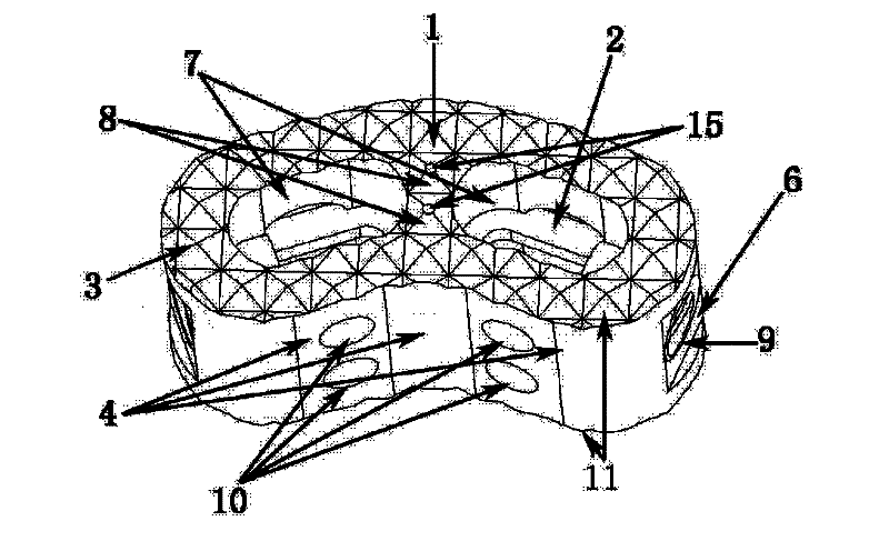
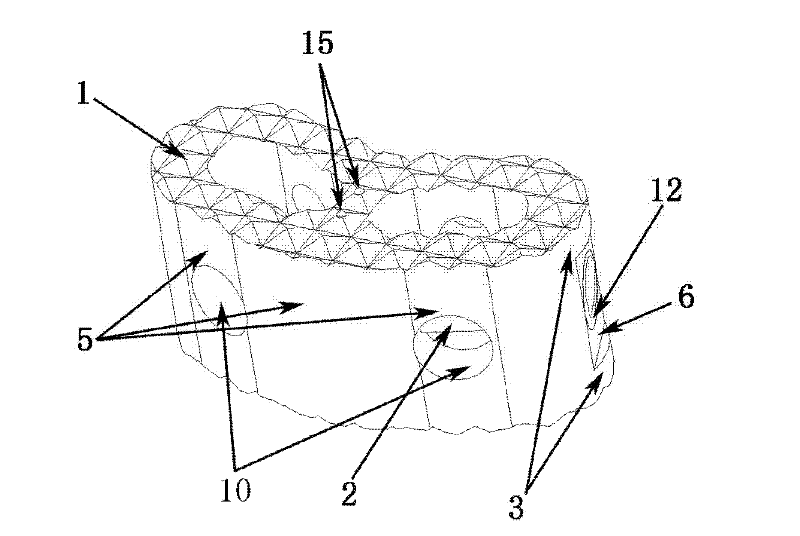
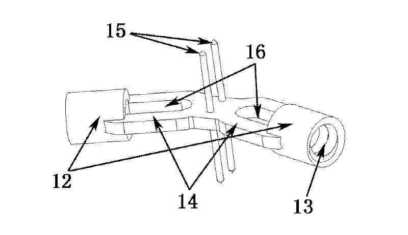
[0039] Such as Figure 1-Figure 6 Shown is the schematic diagram of this embodiment, the main structure 1 of the spinal fusion device is cashew nut-shaped, with an overall width of 14mm, a length of 25mm, a height of 10mm, and a wall thickness of 2.5mm. 0.5mm, can also take any shape that increases the roughness. The base planes of the two bottom surfaces 11 are parallel and have the same shape. The arc-shaped wall in the length direction of the main body is bent to one side at the same time, forming a concave arc-shaped wall 4 on one side and a convex arc-shaped wall 5 on the other side, both of which are left-right symmetrical. The arc-shaped walls on both sides are a plane 6 in the middle section, the main structure includes two hollow holes 7, the two holes have the same shape, and the horizontal direction between the holes is not connected. The cross-sectional shape of the hollow hole 7 is to smoothly connect the arcs at both ends with a straight line. The space occupi...

Embodiment 2

[0043] The structural size of the spinal fusion device is the same as that of Embodiment 1, and the lining reinforcement structure is also the same as that of Embodiment 1. The material used in the spinal fusion cage is the medical implantable PEEK material imported from Germany EVONIK company.

Embodiment 3

[0045] The structural dimensions of the spinal fusion cage are the same as in Embodiment 1, but the fusion cage has an inclination angle of 5 degrees higher at the front and lower at the rear. The width is 14mm, the length is 25mm, the low side is 10mm high, the wall thickness is 2.5mm, and the upper and lower surfaces have anatomical structure. The material used is the medical implantable PEEK material imported by German EVONIK company, which is suitable for patients L4 / L5.


PUM

PropertyMeasurementUnit
Diameteraaaaaaaaaa
Sizeaaaaaaaaaa
Heightaaaaaaaaaa

Abstract

A spinal column fusion device internally lined with reinforced ribs comprises a main body structure and two internally-lined metal reinforced rib structure bodies embedded in the main body structure, wherein the main body structure is of a tubular structure with two hollow holes, each internally-lined metal reinforced rib structure body comprises a metal connecting bridge and two cylinders with internal thread structures, the two cylinders are connected by the metal connecting bridge, and the connecting bridge is embedded in a tube wall of the tubular structure. The horizontal section of the fusion device imitates a spinal column anatomical structure, the whole strength and toughness of the fusion device are improved by a form of internally-lined reinforced ribs, and the selecting range of novel biological materials is enlarged. In the process of an implantation operation, the main body part borne by the internally-lined metal reinforced rib structure is implanted into a body, so thatthe situation that the fusion device can be damaged due to a bad mechanics environment during the operation to influence an operation success can be avoided.

Description

technical field [0001] The invention relates to a spinal fusion device, in particular to a spinal fusion device with inner lining and reinforcement, and belongs to the technical field of medical instruments. Background technique [0002] As an important technique in spinal surgery, intervertebral fusion has been widely used in the treatment of spinal fractures and dislocations, especially in the treatment of degenerative spinal diseases. Spinal fusion device is an effective means to treat spinal diseases such as spinal tuberculosis, infection, deformity, degenerative disease and intervertebral disc injury. [0003] In the 1950s, Cloward first proposed the concept of posterior lumbar intervertebral fusion, which is an ideal spinal fusion from a biomechanical point of view, and has gradually developed into one of the basic techniques of spinal surgery. In 1979, Bagby hollowed stainless steel The perforated column replaces the iliac bone for cervical interbody fusion in horses...

Claims


Application Information

Patent Timeline
IPC IPC(8): A61B17/70A61F2/44
CPCA61F2/44A61F2002/30001
Inventor 崔福斋朱锦文王昶明
Owner BEIJING ALLGENS MEDICAL SCI & TECH
Why Eureka
Try Eureka