Sanitary bottom air exhaust low-temperature spray drying device

A drying device and hygienic technology, applied in the direction of spray evaporation, evaporator accessories, etc., can solve the problems of sticky powder hanging pipe, exhaust air temperature drop, high-temperature melting products cannot be continuously produced, etc., to avoid material retention, The effect of eliminating sanitary dead ends

Pending Publication Date: 2021-02-02
HEILONGJIANG REALGOAL TECHNOLOGY CO LTD
View PDF2 Cites 0 Cited by
  • Summary
  • Abstract
  • Description
  • Claims
  • Application Information

AI Technical Summary

Problems solved by technology

Most of the existing spray drying devices adopt downward cone exhaust or bottom elbow exhaust structure. The exhaust pipe needs to be inserted into the drying room, and the phenomenon of powder sticking to the surface of the exhaust pipe and the inside of the elbow will appear, resulting in the accumulation of powder. Discharge of long-term heating; high heat-sensitivity and high-temperature easy-to-melt products are at the bottom and during the exhaust process, because they are in the exhaust environment, they are easily affected by long-term high-temperature exhaust. When the exhaust temperature exceeds 70°C, it will cause exhaust The product denatures or melts in the wind, which makes it difficult for the powder properties of highly heat-sensitive products to meet the ideal standards, and continuous production of high-temperature melting products cannot be carried out; moreover, in the exhaust air, there is water vapor entrained in the air intake and water evaporated from the material Steam, so the moisture content is high, and the dew point temperature is high. During the exhaust process, the exhaust air temperature will drop through pipeline transportation and powder capture equipment. When the temperature is close to the dew point temperature, the water vapor in the exhaust air will condense and precipitate. Contact with the product will easily cause the product to absorb moisture and condense, making it impossible for continuous production of moisture-absorbing products

Method used


Image

  • Sanitary bottom air exhaust low-temperature spray drying device
  • Sanitary bottom air exhaust low-temperature spray drying device
  • Sanitary bottom air exhaust low-temperature spray drying device

Examples


Embodiment Construction

[0022] The technical solutions in the embodiments of the present invention will be clearly and completely described below in conjunction with the drawings in the embodiments of the present invention.

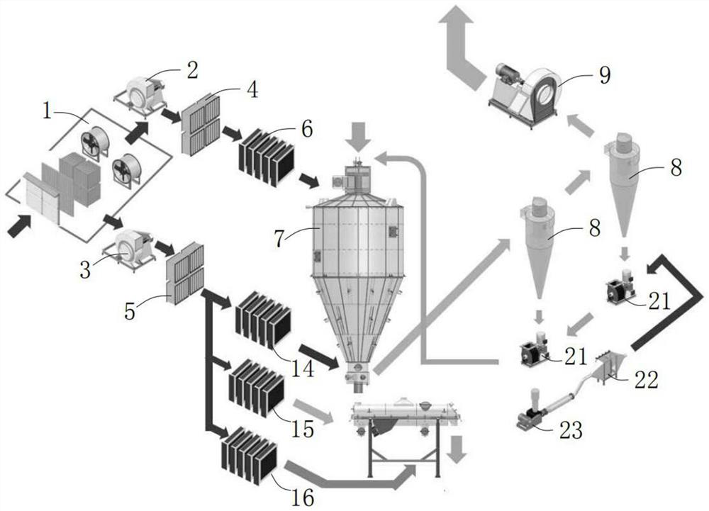
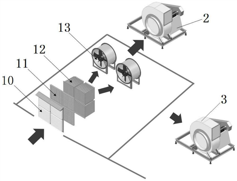
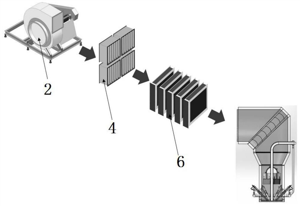
[0023] see Figure 1-6 Description of this embodiment, a sanitary bottom-exhaust low-temperature spray drying device, which includes an air intake chamber 1, a main inlet fan 2, a bed inlet fan 3, a drying tower 7, air heating equipment, dehumidification and heat exchange equipment, and an exhaust mechanism And catch powder mechanism, described drying tower 7 comprises hot blast distributor 17, tower body 18, fixed fluidized bed 19 and vibrating fluidized bed 20, described hot blast distributor 17 links to each other with tower body 18 tops, and described tower body 18 The bottom is connected with the fixed fluidized bed 19, and the fixed fluidized bed 19 is connected with the vibrating fluidized bed 20 through a flexible connection mechanism, and the main inlet fan 2 and the be...


PUM


Abstract

The invention provides a sanitary bottom air exhaust low-temperature spray drying device, belongs to the technical field of spray drying for food, and particularly relates to a sanitary bottom air exhaust low-temperature spray drying device. The problems that serious powder sticking and pipe hanging phenomena exist on the inner side and the outer side of an exhaust pipe of an existing spray dryingdevice, the powder character of a high-heat-sensitivity product cannot meet the standard easily, and high-temperature molten products and products prone to moisture absorption cannot be continuouslyproduced are solved. The device comprises an air taking chamber, a main air inlet fan, a bed air inlet fan, a drying tower, air heating equipment, dehumidification and heat exchange equipment, an airexhaust mechanism and a powder catching mechanism. The main air inlet fan blows air through the air heating equipment, and then the air enters a hot air distributor. The bed air inlet fan blows air through the dehumidification and heat exchange equipment and then divides the air into three paths, the first path enters a fixed fluidized bed, the second path enters the front section of a vibrated fluidized bed and the third path enters the rear section of the vibrated fluidized bed. The spray drying device is mainly used for drying and granulating materials.

Description

technical field [0001] The invention belongs to the technical field of spray drying for food, and in particular relates to a hygienic bottom exhaust low-temperature spray drying device. Background technique [0002] Spray drying device is a device that can complete drying and granulation work, and is widely used in medicine, food and other industries. Most of the existing spray drying devices adopt downward cone exhaust or bottom elbow exhaust structure. The exhaust pipe needs to be inserted into the drying room, and the phenomenon of powder sticking to the surface of the exhaust pipe and the inside of the elbow will appear, resulting in the accumulation of powder. Discharge of long-term heating; high heat-sensitivity and high-temperature easy-to-melt products are at the bottom and during the exhaust process, because they are in the exhaust environment, they are easily affected by long-term high-temperature exhaust. When the exhaust temperature exceeds 70°C, it will cause ex...

Claims


Application Information

Patent Timeline
Patent Type & Authority Applications(China)
IPC IPC(8): B01D1/18B01D1/30
CPCB01D1/18B01D1/30
Inventor 胡正史玥
Owner HEILONGJIANG REALGOAL TECHNOLOGY CO LTD
Why Eureka
Try Eureka