Equipment for machining main connecting journal of crankshaft and end surface of balancing block

A technology of end face processing and balance block, applied in the field of auto parts manufacturing, can solve the problems of low degree of flexibility, large size range and high production cost

Pending Publication Date: 2021-02-02
XIANGYANG FUDA DONGKANG CRANKSHAFT
View PDF0 Cites 0 Cited by
  • Summary
  • Abstract
  • Description
  • Claims
  • Application Information

AI Technical Summary

Problems solved by technology

[0003] 1. Machine tool aging
[0004] 2. Due to the large size range, many models, and frequent model changes of various types of crankshafts, imported machine tools cannot meet the needs of new product development, and imported machine tools are designed according to the original crankshaft structure, and the degree of flexibility is very low
[0005] 3. The price is expensive. If a new production line is added, it is necessary to re-purchase imported machine tools, and the production cost is very high.
[0006] 4. The key parts of imported machine tools cannot be purchased in China, and the replacement is inconvenient. Foreign experts need to be invited for maintenance, which takes a long period and is expensive

Method used


Image

  • Equipment for machining main connecting journal of crankshaft and end surface of balancing block
  • Equipment for machining main connecting journal of crankshaft and end surface of balancing block
  • Equipment for machining main connecting journal of crankshaft and end surface of balancing block

Examples


Embodiment Construction

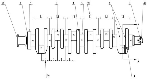
[0065] Such as figure 1 , figure 2 , image 3 , Figure 4 , Figure 5 , Image 6 , Figure 7 , Figure 8 , Figure 9 , Figure 10 , Figure 11 , Figure 12 , Figure 13 , Figure 14 , Figure 15 , Figure 16 , Figure 17 , Figure 18 , Figure 19 , Figure 20 , Figure 21 , Figure 22 , Figure 23 , Figure 24 , Figure 25 , Figure 26 , Figure 27 , Figure 28 , Figure 29 , Figure 30 , Figure 31 , Figure 32 , Figure 33 , Figure 34 , Figure 35 , Figure 36 , Figure 37 , Figure 38 As shown, the fixed support 73 of the present invention is fixed on the left end of the bed 85 with a pressing plate, and the movable support 41 is slidably connected with the guide rail at the upper right end of the bed 85. The movable bracket 41 is connected, and when the crankshaft 4 is processed, the connecting rod 92 is disengaged from the movable bracket 41, and the front ends of the fixed bracket 73 and the movable bracket 41 are equipped with an axi...


PUM


Abstract

The invention relates to equipment for machining a main connecting journal of a crankshaft and an end surface of a balancing block, which is used for machining the crankshaft automatically. A fixed bracket is fixed to the left end of a machine tool body, a movable bracket is slidably connected to the right end of the machine tool body and is connected to a right sliding table through a connectingrod, clamping apparatuses are mounted at the front ends of the two brackets, and an angular positioning device is arranged on an angular positioning clamping apparatus; a cutterhead is driven by a cutterhead spindle to rotate and is fed in perpendicular, vertical and transverse direction; and a milling head box is mounted on a frame, the frame is connected to a sliding table, the sliding table isconnected to a guide rail of the machine tool body, a center rack is connected to a left sliding table, and a skipping distance L between the center rack and the cutterhead on the left side is a center distance between the main journal and an adjacent connecting rod neck. The equipment further comprises a lug type follow-up lifting tool and a cutterhead debugging worktable. It is only needed to detach the crankshaft manually and the crankshaft is clamped automatically by using a hydraulic clamping apparatus, so that the main journal, the connecting journal and the end surface of the balancingblock of the crankshaft can be machined at one time automatically. The equipment can be suitable for machining various crankshafts, and it is convenient to replace the machine tool in type and the equipment is very high in degrees of automation and flexibility.

Description

technical field [0001] The invention relates to the technical field of auto parts manufacturing, in particular to a processing device for crankshaft main journals, connecting rod journals and end faces of balance blocks of main connecting journals. Background technique [0002] The structure of crankshaft 4 is generally composed of main journal 5, connecting rod journal 3, crank arm, balance weight, big end and small end (such as figure 1 shown). There is a certain eccentricity R between the main journal 5 and the connecting rod journal 3 of the crankshaft 4, which is very troublesome for ordinary machine tools. Commonly used ordinary lathes can only process the main journal 5, but the connecting rod journal 3 with the eccentricity R and the two sides of the balance weight are difficult to complete on ordinary lathes. It is very troublesome to install and use the special fixture. Imported internal milling machine tools can also be used for the machining of the main journa...

Claims


Application Information

Patent Timeline
Patent Type & Authority Applications(China)
IPC IPC(8): B23C3/06B23Q3/12B23C9/00
CPCB23C3/06B23C9/00B23Q3/12
Inventor 杨军肖梦婕
Owner XIANGYANG FUDA DONGKANG CRANKSHAFT
Why Eureka
Try Eureka