Eureka AIR delivers breakthrough ideas for toughest innovation challenges, trusted by R&D personnel around the world.

Flange positioning device, positioning system and positioning method

A positioning device and flange technology, applied in auxiliary devices, applications, auxiliary welding equipment, etc., can solve the problems of high cost and low practicability

Inactive Publication Date: 2021-02-02
GUANGZHOU WENCHONG SHIPYARD CO LTD
View PDF5 Cites 2 Cited by
  • Summary
  • Abstract
  • Description
  • Claims
  • Application Information

AI Technical Summary

Problems solved by technology

At this stage, the positioning of the flange is carried out through the flange fixture. The flange fixture includes a fixing seat, and the fixing seat is provided with a positioning pin hole. The flange is fixed on the fixing seat and the bolt hole of the flange is aligned with the positioning pin hole. Alignment, and then use the positioning pin to penetrate the bolt hole and the positioning pin hole in turn to complete the positioning of the flange; however, the existing flange fixture only has one positioning pin hole on the fixing seat, which can only be used for The positioning of one type of flange is not very practical, and multiple flange fixtures are required to complete the positioning of various types of flanges, which costs a lot

Method used


Image

  • Flange positioning device, positioning system and positioning method
  • Flange positioning device, positioning system and positioning method
  • Flange positioning device, positioning system and positioning method

Examples


Embodiment Construction

[0028] The specific implementation manners of the present invention will be further described in detail below in conjunction with the accompanying drawings and embodiments. The following examples are used to illustrate the present invention, but are not intended to limit the scope of the present invention.

[0029] In the description of the present invention, it should be understood that the terms "first", "second", etc. are used in the present invention to describe various information, but these information should not be limited to these terms, and these terms are only used to describe the same type of information are separated from each other. For example, "first" information may also be referred to as "second" information without departing from the scope of the present invention, and similarly, "second" information may also be referred to as "first" information.

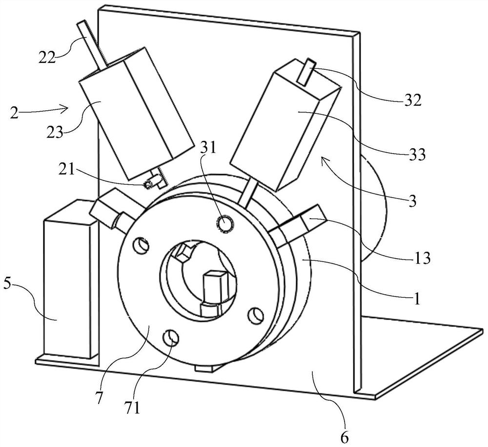
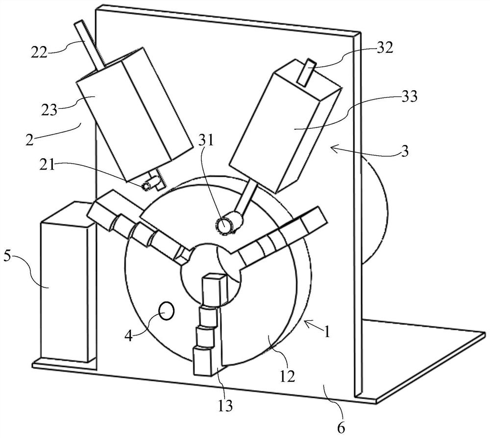
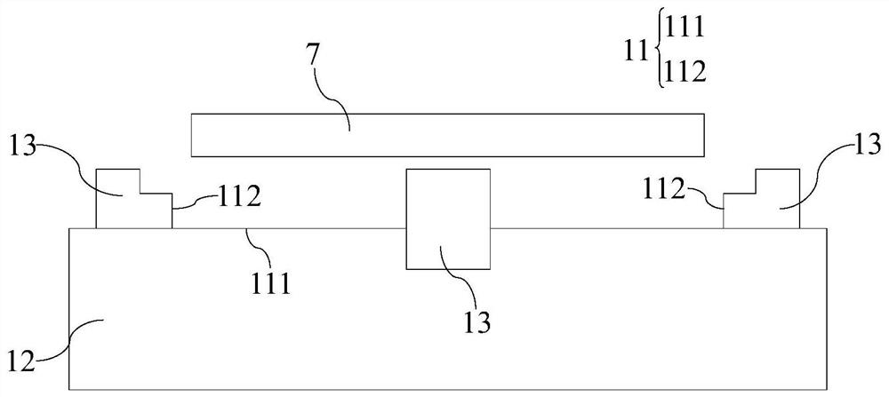
[0030] Such as Figure 1-Figure 4 As shown, the preferred embodiment of the present invention provides a flan...


PUM


Abstract

The invention discloses a flange positioning device. The flange positioning device comprises a chuck, a first positioning mechanism, a second positioning mechanism, a positioning inductor and a control terminal, wherein the chuck is equipped with a first limiting surface and a second limiting surface; the first limiting surface and the second limiting surface define a limiting slot for limiting flange movement; the first positioning mechanism comprises a first positioning plug pin capable of moving relative to the limiting slot; the second positioning mechanism comprises a second positioning plug pin capable of moving relative to the limiting slot; the outer diameter of the first positioning plug pin is smaller than that of the second positioning plug pin; the positioning inductor is arranged in the limiting slot; and the chuck, the first positioning mechanism, the second positioning mechanism and the positioning inductor are electrically connected to the control terminal. The flange positioning device can position flanges of various models, is high in practicability and is high in economic benefit. The invention further discloses a flange positioning system and a flange positioning method. The system can save time of regulating a flange position, improves assembly efficiency of the flange and a tube. The method is simple and easy to implement, and is precise in positioning.

Description

technical field [0001] The invention relates to the technical field of pipeline installation, in particular to a flange positioning device, a positioning system and a positioning method thereof. Background technique [0002] When welding the flange and the pipe, it is necessary to position the flanges at both ends of the pipe first, so that the positions of the two flanges relative to the end of the pipe are consistent, so as to facilitate the subsequent welding of the flange and the pipe. At this stage, the positioning of the flange is carried out through the flange fixture. The flange fixture includes a fixing seat, and the fixing seat is provided with a positioning pin hole. The flange is fixed on the fixing seat and the bolt hole of the flange is aligned with the positioning pin hole. Alignment, and then use the positioning pin to penetrate the bolt hole and the positioning pin hole in turn to complete the positioning of the flange; however, the existing flange fixture o...

Claims


Application Information

Patent Timeline
Patent Type & Authority Applications(China)
IPC IPC(8): B23K37/053B23K101/06
CPCB23K37/0536B23K2101/06
Inventor 苏士斌吴玉辉王兰蓝初广李成银
Owner GUANGZHOU WENCHONG SHIPYARD CO LTD
Why Eureka
Eureka Blog
Learn More