Grinding machine for pipe grinding with single-side chamfering and grinding function

A grinding machine, unilateral technology, applied in the direction of machine tools suitable for grinding workpiece edges, cleaning methods using tools, cleaning methods and utensils, etc., can solve operator burns, debris splashing, poor heat dissipation of drive motors, etc. question

Active Publication Date: 2021-02-02
重庆泊利玺智能科技有限公司
View PDF12 Cites 4 Cited by
  • Summary
  • Abstract
  • Description
  • Claims
  • Application Information

AI Technical Summary

Problems solved by technology

[0004] The purpose of the present invention is to solve the problem that when the existing pipe grinding machine in the prior art grinds the pipe, when the grinding device grinds the pipe, a large amount of debris with high temperature will be generated, and the debris will splash during grinding, which is easy It will cause burns to the operator, and under long-term grinding, the driving motor on the grinding device will generate a lot of heat, the heat dissipation effect on the driving motor is poor, and it is easy to cause damage to the driving motor. The grinding machine is suitable for grinding pipes and has the function of single-side chamfering and grinding. It can cool the high-temperature debris generated during grinding and cool the drive motor on the grinding device to ensure the normal operation of the grinding device. Work

Method used


Image

  • Grinding machine for pipe grinding with single-side chamfering and grinding function
  • Grinding machine for pipe grinding with single-side chamfering and grinding function
  • Grinding machine for pipe grinding with single-side chamfering and grinding function

Examples


Embodiment Construction

[0023] The following will clearly and completely describe the technical solutions in the embodiments of the present invention with reference to the accompanying drawings in the embodiments of the present invention. Obviously, the described embodiments are only some, not all, embodiments of the present invention.

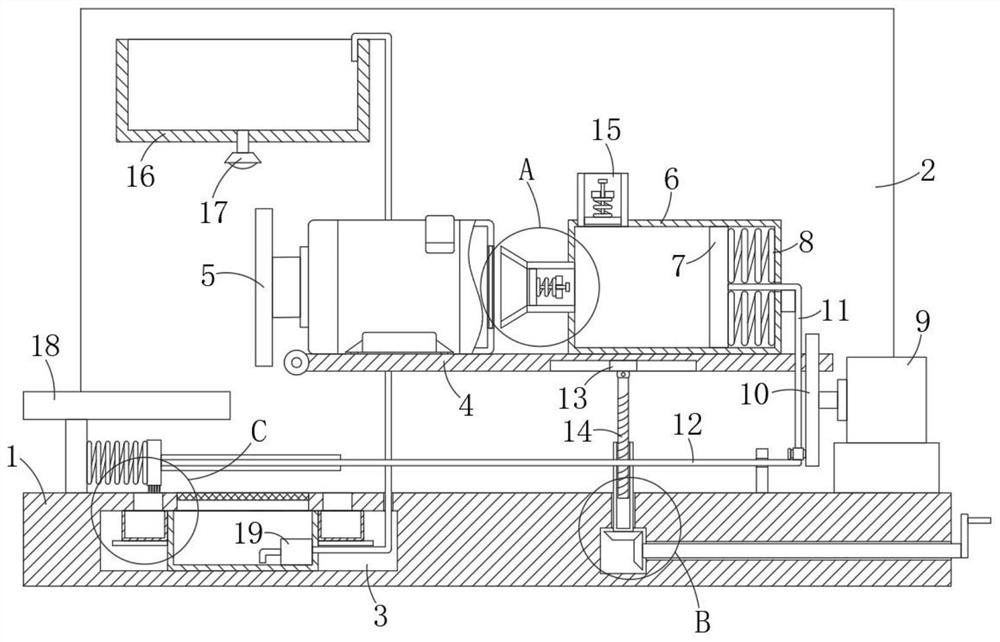
[0024] refer to Figure 1-4 , a grinding machine for grinding pipes and having the function of unilateral chamfering and grinding, comprising a base 1, a mounting plate 2 is fixedly installed on the top of the base 1, and a spraying mechanism is arranged on the mounting plate 2, and the spraying mechanism includes a fixed mounting on the mounting plate The water storage basin 16 on the front side wall of the plate 2, the bottom of the water storage basin 16 is fixedly installed with a nozzle 17 communicating with the interior thereof;

[0025] The base 1 is provided with a placement groove 3 and an installation cavity 25, and the inner top of the placement groove 3 i...


PUM


Abstract

The invention discloses a grinding machine for pipe grinding with a single-side chamfering and grinding function. The grinding machine comprises a base, wherein a mounting plate is fixedly mounted atthe top of the base, a spraying mechanism is arranged on the mounting plate, and a placing groove and a mounting cavity are formed in the base. A mounting groove and two communicating ports which communicate with the interior of the placing groove are formed in the inner top of the placing groove in a penetrating mode, a filter screen is fixedly mounted in the mounting groove, a collecting mechanism is arranged in the placing groove, the collecting mechanism penetrates through the base and extends into the spraying mechanism, and a placing plate is rotatably connected to the front side wall ofthe mounting plate. A grinding device is fixedly mounted at the top of the placing plate, a cooling mechanism is arranged at the top of the placing plate, and a grinding table is fixedly mounted at the top of the base. The grinding device is reasonable in structural design, when a pipe is ground, high-temperature chippings generated during grinding can be cooled, a driving motor on the grinding device can also be cooled, and normal work of the grinding device is guaranteed.

Description

technical field [0001] The invention relates to the technical field of pipe grinding equipment, in particular to a grinding machine for grinding pipes and having the function of single-side chamfering and grinding. Background technique [0002] After the pipe is produced, there will be many burrs on the surface and cross-section of the pipe. If it is not treated, it will easily cause scratches to the user during use. Therefore, after the pipe is produced, it is necessary to remove the burrs on the pipe. Clean up to avoid injury to the user's body when in use. [0003] In the prior art, when the existing pipe grinding machine grinds the pipe, when the grinding device grinds the pipe, a large amount of debris with high temperature will be generated, and the debris will splash during the grinding, which will easily cause burns to the operator. And under long-term grinding, the driving motor on the grinding device will generate a lot of heat, the heat dissipation effect on the ...

Claims


Application Information

Patent Timeline
IPC IPC(8): B24B55/03B24B55/12B08B1/00B24B9/00H02K5/20H02K9/04
CPCB24B55/03B24B55/12B24B9/00B24B9/007H02K5/20H02K9/04B08B1/12Y02P70/10
Inventor 吴明
Owner 重庆泊利玺智能科技有限公司
Why Eureka
Try Eureka