Angle adjustable fiber product cutting machine

A fiber product and cutting machine technology, which is applied in the field of fiber product processing, can solve the problems of inconvenient adjustment of the angle of fiber products, dust pollution of the environment, and damage to the health of workers.

Inactive Publication Date: 2021-02-02
连云港新东方家纺有限公司
View PDF1 Cites 2 Cited by
  • Summary
  • Abstract
  • Description
  • Claims
  • Application Information

AI Technical Summary

Problems solved by technology

An angle-adjustable fiber product cutting machine in the above-mentioned patent has the following disadvantages: it is inconvenient to adjust the angle of fiber products, and debris and dust seriously pollute the environment and damage the health of workers

Method used


Image

  • Angle adjustable fiber product cutting machine
  • Angle adjustable fiber product cutting machine
  • Angle adjustable fiber product cutting machine

Examples


Embodiment 1

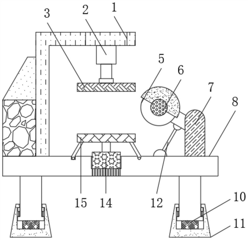
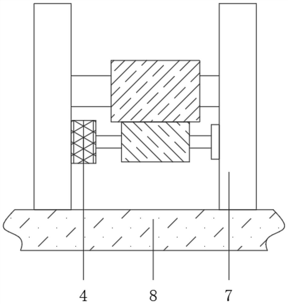
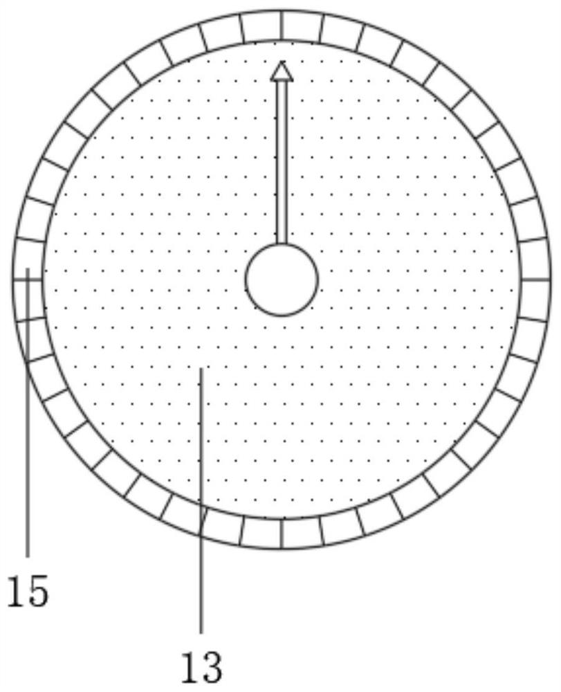
[0027] refer to Figure 1-4 , an angle-adjustable fiber product cutting machine, including a base 8, an L-shaped side plate 1 is installed on one side of the top outer wall of the base 8 through bolts, and a hydraulic column 2 is fixedly installed on the outer wall of the bottom end of the L-shaped side plate 1, and the hydraulic column 2 The bottom end is rotatably connected with the pressure plate 3, the middle of the base 8 is inlaid with a third motor 14, and the upper end of the third motor 14 is installed with a cutting table 13 through the rotating shaft, and the outer wall of the cutting table 13 is rotated and socketed with an angle plate 15 , the other two ends of the outer wall at the top of the base 8 are installed with a fixed plate 7 through bolts, and the upper ends of the inner walls of the two fixed plates 7 are fixedly installed with a rotating shaft, and the outer wall of the outer wall of the rotating shaft is fixedly sleeved with a gear rod. The first moto...

Embodiment 2

[0037] refer to Figure 5 , an angle-adjustable fiber product cutting machine, further, a ring groove 16 is opened at the top of the base 8, and a negative pressure collection tank 17 is installed at the bottom of the base 8 through bolts.

[0038] Working principle: Dust, debris, etc. are attracted to the negative pressure collection tank 17 through the ring groove 16, so as to avoid serious pollution of the environment by debris and dust and damage to the health of workers.


PUM


Abstract

The invention belongs to the technical field of fiber product processing, in particular to an angle adjustable fiber product cutting machine. In order to solve the problems that in the prior art, it is inconvenient to adjust a fiber product, fragments and dust pollute the environment severely and the physical health of a worker is harmed, the invention provides a scheme as follows: the angle adjustable fiber product cutting machine comprises a base. An L-shaped side plate is mounted on one side of the outer wall of the top end of the base through bolts, a hydraulic column is fixedly mounted onthe outer wall of the bottom end of the L-shaped side plate, the bottom end of the hydraulic column is rotatably connected to a pressure plate in a sleeving manner through a bearing, a third motor isinlaid in the middle of the base, a cutting table is rotatably mounted at the upper end of the third motor through a rotating shaft, and an angle plate is rotatably connected to the outer peripheralwall of the cutting table in a sleeving manner. As a fiber plate block is located between the pressure plate and the cutting table, along with work of the third motor, the cutting table and the angleplate are rotatably connected in a clamped manner, so that the fiber plate block, the pressure plate and the cutting table rotate integrally at needed angles. A second motor works, and a cutting wheelrotates to cut an angle of the fiber plate block.

Description

technical field [0001] The invention relates to the technical field of fiber product processing, in particular to an angle-adjustable fiber product cutting machine. Background technique [0002] Fiber refers to a substance composed of continuous or discontinuous filaments, which can be natural or synthetic; fiber plays an important role in maintaining tissues in animals and plants; fiber has a wide range of uses and can be woven into thin threads, Thread ends and hemp rope can also be woven into fiber layers when making paper or felt; they are also commonly used to make other materials and form composite materials with other materials; they are also combined with high technology to make missiles resistant to high temperatures and river embankments to Prevent collapse, cement can prevent cracking, blood vessels and nerves can be repaired, etc. [0003] Fiber cutting machine is a general-purpose cutting equipment with a wide range of applications. It can cut a variety of diff...

Claims


Application Information

Patent Timeline
Patent Type & Authority Applications(China)
IPC IPC(8): B26D1/16B26D5/08B26D7/20B26D7/02B26D7/26B26D7/18B26D7/00B08B17/02F16F15/02
CPCB08B17/02B26D1/16B26D5/086B26D7/00B26D7/025B26D7/1863B26D7/20B26D7/2621F16F15/02
Inventor 诸其林周小兰俞丽丽尹倩倩
Owner 连云港新东方家纺有限公司
Why Eureka
Try Eureka