Composite material bearingless rotor wing stability augmentation device

A stabilization device and composite material technology, applied in special data processing applications, instruments, electrical digital data processing, etc., to achieve the effect of improving calculation efficiency and optimal aeroelastic stability

Inactive Publication Date: 2021-02-02
BEIHANG UNIV
View PDF6 Cites 1 Cited by
  • Summary
  • Abstract
  • Description
  • Claims
  • Application Information

AI Technical Summary

Problems solved by technology

Since there are no pendulum hinges, flapping hinges, and pitch-variable hinges in this structure, a flexible beam structure is used at the root of the blade, and the blade often adopts an in-plane soft structure, which makes the aerodynamic-structural coupling problem of this rotor structure more prominent.

Method used


Image

  • Composite material bearingless rotor wing stability augmentation device
  • Composite material bearingless rotor wing stability augmentation device
  • Composite material bearingless rotor wing stability augmentation device

Examples


Embodiment

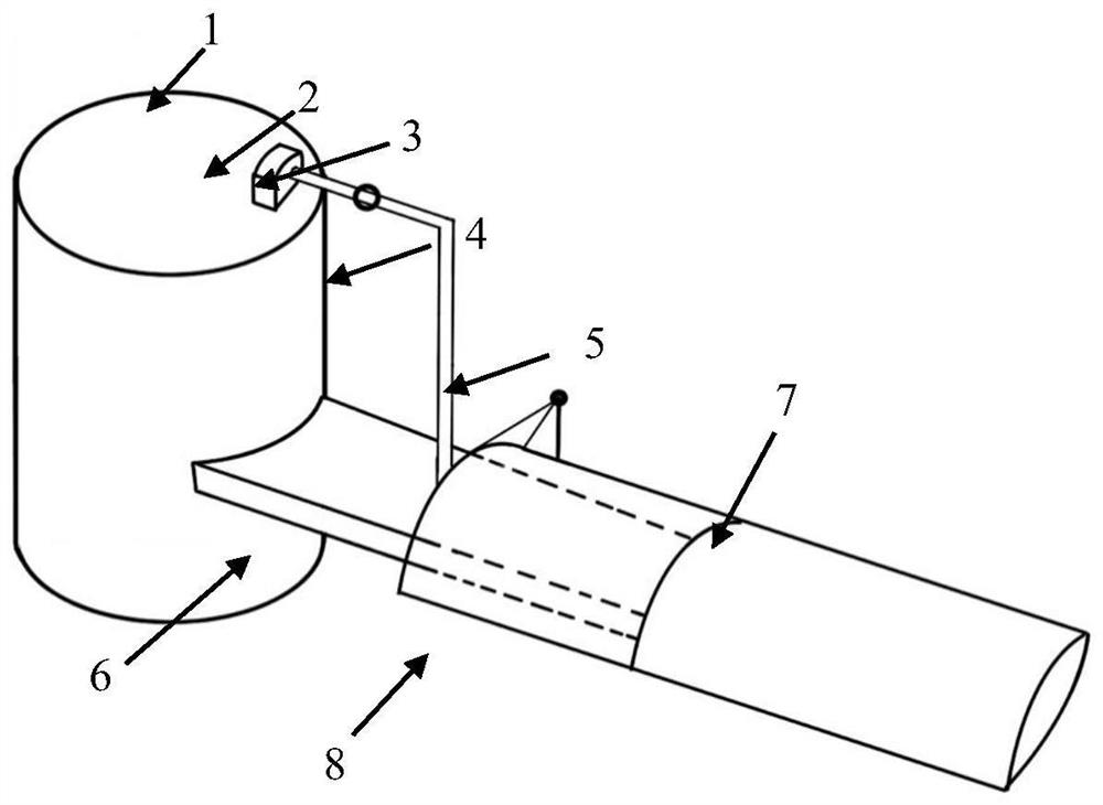
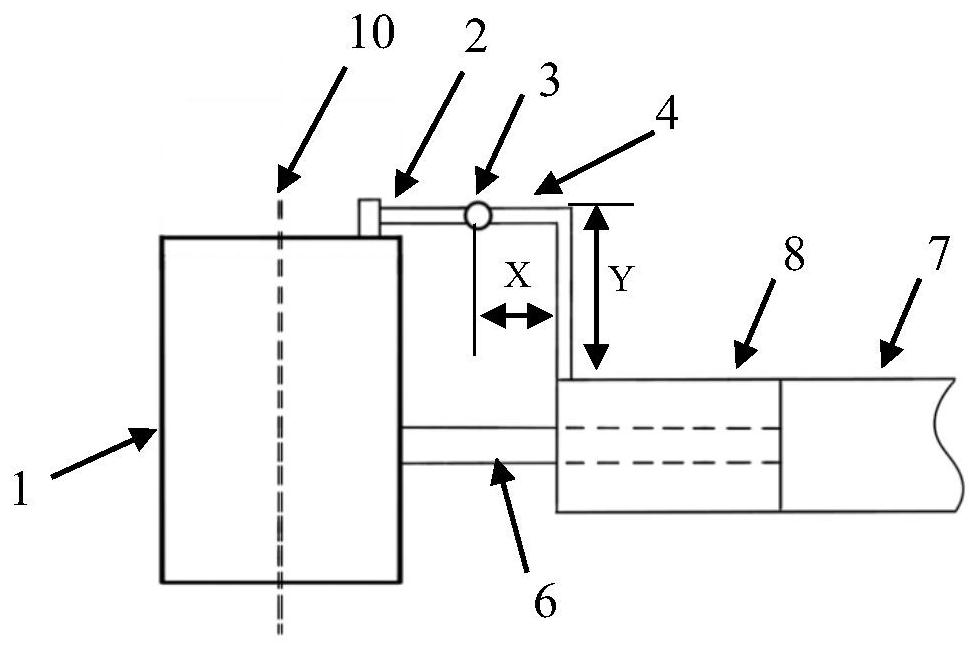
[0107] The characteristic parameters of a bearingless rotor are as follows: number of blades N=4, rotor radius R=0.96m, chord length c=0.081m, rotor rated speed Ω=817rpm. The radius of the circular shimmy pin, the length of the horizontal part and the length of the vertical part are used as design variables. In order to simplify the calculation process, the shimmy pin is set as a rigid body structure in this example, so the radius basically has no effect on it, while the shimmy pin The length of the horizontal part is the minimum, that is, X=0. At this time, the shimmy pin is directly connected to the propeller hub through the central support 5, and the design interval of the vertical part length of the shimmy pin is [0 0.012R]. The technical solution provided by the present invention is obtained: when the length of the vertical part of the shimmy pin is 0.012R, the real part of the eigenvalue representing the aeroelastic stability is the smallest, that is, the shimmy damping i...


PUM


Abstract

The invention provides a composite material bearingless rotor wing stability augmentation device. According to the device, an L-shaped shimmy pin composed of a vertical part and a horizontal part is additionally arranged between a helicopter rotor hub and a torsion sleeve. A method comprises the following steps: determining a design variable of the device and a value range of the design variable,forming a design space, establishing a structure model and an aerodynamic model of a reference model, and acquiring a corresponding aerodynamic reduced-order model by analyzing a modal of a finite element model of the reference model; taking the modal of the reference model as an assumed modal to obtain a reduced-order model of the parameterized finite element model; performing aeroelasticity analysis on the parameterized model; taking the lengths and the section radius sizes of the horizontal part and the vertical part of the shimmy pin as design variables, selecting the design variables as input in a design space, and taking aeroelastic stability analysis as output to obtain an agent model of the parameterized model; and on the basis of the agent model, taking the upper limit and the lower limit of the design space as constraint conditions, and subjecting the shimmy pin to optimization design to obtain the bearingless rotor wing structure with the optimal aeroelastic stability.

Description

technical field [0001] The invention relates to a design of an aircraft, in particular to a design method of a shimmy pin device for improving the aeroelastic stability of a bearingless rotor helicopter. Background technique [0002] The rotor is the key component to generate the lift, forward thrust and control force required for helicopter flight. The design and analysis of the rotor and its associated structure is the key technology of helicopter design. According to the configuration, the metal structure propeller hub commonly used in existing helicopters is divided into articulated, semi-articulated, hingeless, and bearingless rotor systems. Among them, the bearingless rotor system is the most advanced, which can effectively avoid the defects of traditional structures such as complex structure, heavy weight, high maintenance cost, and limited service life. Therefore, the advent of this propeller hub is of great significance to the development of helicopter technology. ...

Claims


Application Information

Patent Timeline
Patent Type & Authority Applications(China)
IPC IPC(8): G06F30/15G06F30/17G06F30/23G06F111/04G06F119/14
CPCG06F30/15G06F30/17G06F30/23G06F2111/04G06F2119/14Y02T90/00
Inventor 李道春陈世泽赵仕伟阚梓向锦武
Owner BEIHANG UNIV
Why Eureka
Try Eureka