Rescue device for adjusting drowning automobile orientation through buoyancy

A technology of buoyancy and automobiles, which is applied in circuit devices, water lifesaving, electric vehicles, etc. It can solve problems such as difficult to open the door to escape, difficult for people in the vehicle to escape, contact with water or submerged in water, etc.

Active Publication Date: 2021-02-05
SHAANXI UNIV OF SCI & TECH
View PDF10 Cites 5 Cited by
  • Summary
  • Abstract
  • Description
  • Claims
  • Application Information

AI Technical Summary

Problems solved by technology

[0002] With the development of science and technology, automobiles have rapidly developed to a very high level. Nowadays, automobiles not only have the function of transportation, but also have powerful functions in terms of safety performance. Generally, the more common automobile safety protection devices are safety protection devices. The airbag pops up in the event of a collision to protect the driver to a certain extent; however, the airbag is only aimed at the situation of a collision on the road. Once the vehicle is filled with water, it is difficult for people in the vehicle to open due to the effect of water pressure Escape from the car door, especially when the car is completely overturned and the bottom of the car falls into the water, it is even more difficult for the people in the car to escape;
[0003] The publication number is [CN106740629 A], and the patent document titled a kind of anti-sinking protection device and automobile discloses a protection device for anti-sinking in water, which includes a gas storage tank and a plurality of airbags, wherein the plurality of airbags are respectively arranged in the vehicle. The position between the chassis, the top, and the front and rear tires on both sides, and each air bag is connected to the air storage tank through the air guide tube; an inflation control valve is installed on the air guide tube near the air outlet of the air storage tank, and the inflation air valve is connected to the air tank. The car controller is electrically connected, and a water detection element is installed on the car chassis, and the water detection element is also electrically connected to the car controller; when the car is running normally, each airbag is not inflated and is arranged on the chassis, top and both sides of the car position...Furthermore, an air pump is provided near the head of the car, and the air pump is connected to the car engine through an electromagnetic clutch transmission. The water detection element of the chassis is activated, and the airbags at each position will be directly triggered only when the chassis of the car touches the water first, but once the chassis of the car falls into the water, the water detection element of the chassis will not immediately touch the water, so it cannot be triggered quickly Start the air bag, and although the roof of this invention is provided with an air bag, when the chassis faces upwards and falls into the water, the air bag on the roof can only produce buoyancy to the car, but the car is still in the upward posture of the chassis, and the doors on both sides of the car are closed. It is possible to be in contact with the water surface or submerged in the water, and the driver's head in the car is facing down, which cannot guarantee the escape of the people in the car. At the same time, the air pump of this invention is electrically connected to the power supply element of the car itself, that is, Before the vehicle collides into the water, when the power supply element of the vehicle itself is damaged due to the collision, the air pump will not be able to start at all, so that the airbag will not be able to carry the car up to the surface.

Method used


Image

  • Rescue device for adjusting drowning automobile orientation through buoyancy
  • Rescue device for adjusting drowning automobile orientation through buoyancy
  • Rescue device for adjusting drowning automobile orientation through buoyancy

Examples


Embodiment Construction

[0025] The following will clearly and completely describe the technical solutions in the embodiments of the present invention with reference to the accompanying drawings in the embodiments of the present invention. Obviously, the described embodiments are only some, not all, embodiments of the present invention. Based on the embodiments of the present invention, all other embodiments obtained by persons of ordinary skill in the art without making creative efforts belong to the protection scope of the present invention.

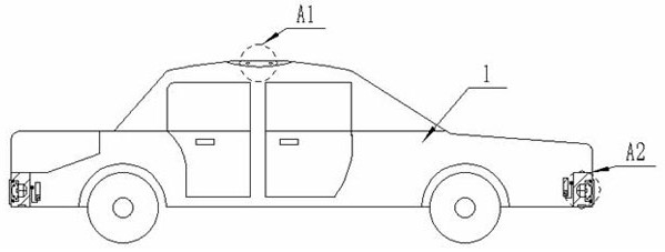
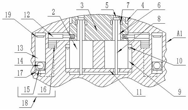
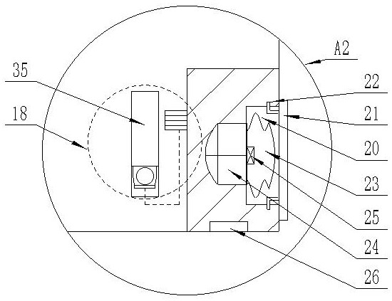
[0026] see Figure 1-6, a rescue device for adjusting the direction of a vehicle falling into water by buoyancy. The inside of the cavity 20 is folded and accommodated with a square buoyancy airbag 23, and a one-way air valve-25 is fixedly connected between the square buoyancy airbag 23 and the air outlet of the first high-pressure rapid inflation pump 24, and the direction of the one-way air valve-25 is the first A high-pressure fast air pump 24 is directed ...


PUM


Abstract

A rescue device for adjusting the direction of an automobile falling into water through buoyancy comprises an automobile body; storage cavities are formed in the automobile head and the automobile tail of the automobile body correspondingly, first high-pressure quick inflation pumps are embedded in the inner walls of the storage cavities, square buoyancy air bags are folded and stored in the storage cavities, and an annular storage box body is embedded in an automobile body shell; meanwhile, the annular storage box body is located on the side close to the driving position of the vehicle body,and an annular buoyancy airbag is folded and stored in the annular storage box body. When an automobile falls into a lake during running and the bottom of the automobile is downward, the first pressure induction switch enables the first high-pressure rapid inflation pump to rapidly inflate the square buoyancy air bag, the square buoyancy air bag is inflated and unfolded, the square buoyancy air bags at the head and the tail of the automobile body generate buoyancy on the water surface, and the automobile body is prevented from sinking into water; when the automobile turns over and falls into water, the annular buoyancy air bag is triggered, so that the automobile door at the automobile driving position floats upwards on the water surface, and escape is facilitated.

Description

technical field [0001] The invention belongs to the technical field of protection devices for vehicles falling into water, and in particular relates to a rescue device for adjusting the orientation of vehicles falling into water by buoyancy. Background technique [0002] With the development of science and technology, automobiles have rapidly developed to a very high level. Nowadays, automobiles not only have the function of transportation, but also have powerful functions in terms of safety performance. Generally, the more common automobile safety protection devices are safety protection devices. The airbag pops up in the event of a collision to protect the driver to a certain extent; however, the airbag is only aimed at the situation of a collision on the road. Once the vehicle is filled with water, it is difficult for people in the vehicle to open due to the effect of water pressure Escape from the car door, especially when the car is completely overturned and the bottom ...

Claims


Application Information

Patent Timeline
Patent Type & Authority Applications(China)
IPC IPC(8): B63C9/08B63C9/00B60R21/00H02N2/18H02J7/32
CPCB63C9/08B63C9/00B60R21/00H02N2/186H02J7/32B63C2009/0029B60R2021/0016B60R21/013B60R2021/01211B60R21/01
Inventor 尚宪茹刘子建
Owner SHAANXI UNIV OF SCI & TECH
Why Eureka
Try Eureka