Unmanned aerial vehicle with camera protection device

A protective device and drone technology, applied in the field of drones, can solve problems such as the impact of taking pictures and the ability to adapt to the environment to be improved, and achieve the effects of automatic camera protection, strong practicability, and clear shooting

Inactive Publication Date: 2021-02-05
张云
View PDF0 Cites 1 Cited by
  • Summary
  • Abstract
  • Description
  • Claims
  • Application Information

AI Technical Summary

Problems solved by technology

[0003] During the flight of the existing UAV, if it encounters severe weather conditions, rain and snow will affect the photo taking, and the adaptability to the environment needs to be improved

Method used


Image

  • Unmanned aerial vehicle with camera protection device
  • Unmanned aerial vehicle with camera protection device
  • Unmanned aerial vehicle with camera protection device

Examples


Embodiment 1

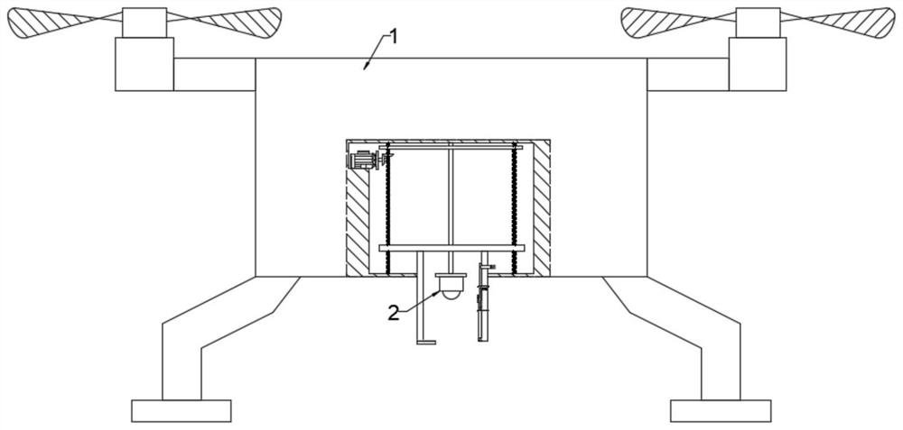
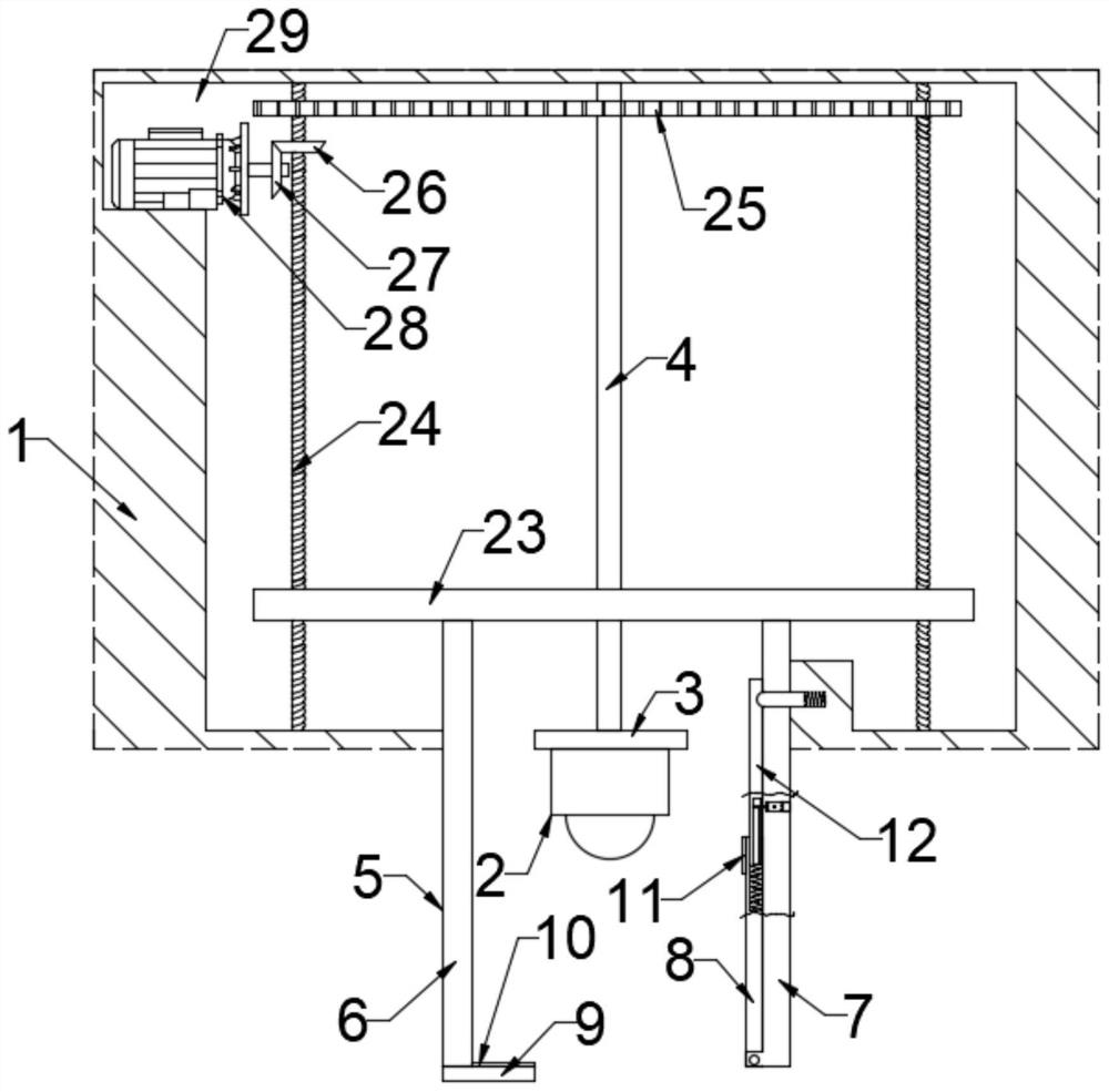
[0025] see Figure 1-5 , a drone with a camera protection device, comprising a body 1, a remote control device and a camera 2, the body 1 is provided with an empty slot 29, the empty slot 29 is fixedly connected with a connecting rod 4, and the connecting rod 4 is fixedly connected with a mounting plate 3. The camera 2 is installed on the mounting plate 3, the outer side of the camera 2 is provided with a protective plate 5 slidingly connected with the body 1, the protective plate 5 is a hollow square enclosure, and the hollow groove 29 is provided with a protective plate 5 fixedly connected mobile plate 23, the mobile plate 23 is connected with a drive mechanism to drive it to move, the drive mechanism is wirelessly connected to the remote control device, one side of the protective plate 5 is the first side plate 6, and the first side plate 6 is fixedly connected There is a placement plate 9, on which a first magnetic plate 10 is installed, and the side of the protection plat...

Embodiment 2

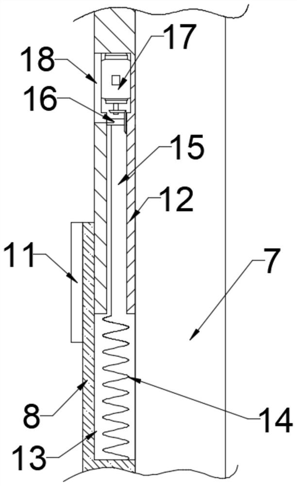
[0030] This embodiment is expanded on the basis of Embodiment 1. A reset mechanism is provided between the flip protection plate 8 and the inserting plate 12. The reset mechanism includes an empty slot 15 provided on the inserting plate 12, and the empty slot 15 rotates. A reel 16 is connected, and the reel 16 is connected with a first micro-motor 17 that drives it to rotate, and the first micro-motor 17 is wirelessly connected with the remote control device, and the outer side of the first micro-motor 17 is provided with an end that is fixedly connected with the plugboard 12 through bolts. Cover 18, the flip protection plate 8 is provided with a first chute 13 matched with the inserting plate 12, the bottom wall of the first chute 13 communicates with the inserting plate 12, and the bottom wall of the first chute 13 is fixedly connected with a Elastic rope 14 on 16, after rain and snow passed, by remote control device control first micromotor 17 rotates, and first micromotor 1...


PUM


Abstract

The invention discloses an unmanned aerial vehicle with a camera protection device. The unmanned aerial vehicle comprises a vehicle body, a remote control device and a camera, a protection plate slidably connected with the vehicle body is arranged on the outer side of the camera, the protection plate is a hollow square surrounding plate, a moving plate fixedly connected with the protection plate is arranged in an empty groove, and the moving plate is connected with a driving mechanism for driving the moving plate to move; the driving mechanism is in wireless connection with the remote controldevice, one side face of the protection plate is a first side plate, the first side plate is fixedly connected with a containing plate, a first magnetic plate is installed on the containing plate, theface, opposite to the first side plate, of the protection plate is a second side plate, and the second side plate is hinged to an overturning protection plate attached to the second side plate. And asecond magnetic plate matched with the first magnetic plate is arranged on the outer side of the movable end of the turnover protection plate, the turnover protection plate is made of a transparent material, and the turnover protection plate is connected with a triggering mechanism for triggering the turnover protection plate to turn over. The unmanned aerial vehicle is ingenious in structure andhas the effect of protecting the camera in severe weather.

Description

technical field [0001] The invention relates to the field of unmanned aerial vehicles, in particular to an unmanned aerial vehicle with a camera protection device. Background technique [0002] Unmanned aircraft, referred to as "unmanned aerial vehicle", or "UAV" in English, is an unmanned aircraft that is controlled by radio remote control equipment and its own program control device, or is completely or intermittently operated autonomously by an on-board computer. According to the application field, UAV can be divided into military and civilian. In terms of military use, UAVs are divided into reconnaissance aircraft and target aircraft. In terms of civilian use, drones + industry applications are the real rigid needs of drones; currently, they are used in aerial photography, agriculture, plant protection, micro selfies, express delivery, disaster relief, wildlife observation, infectious disease monitoring, surveying and mapping, news reports, power patrols, etc. Inspecti...

Claims


Application Information

Patent Timeline
Patent Type & Authority Applications(China)
IPC IPC(8): B64D47/08B64C27/08
CPCB64D47/08B64C27/08B64U10/10B64U2101/30
Inventor 张云
Owner 张云
Why Eureka
Try Eureka