A mechanical winding device for textile technology

A winding device and mechanical technology, which are applied in the directions of transportation and packaging, thin material handling, and transportation of filamentous materials, etc., can solve the problems of lack of pressure protection for yarns, poor use effect, and uneven winding, etc. Disassembly and maintenance, improve work efficiency, improve the effect of winding quality

Inactive Publication Date: 2022-05-03
泰安岱银新宇纺织有限公司
View PDF18 Cites 0 Cited by
  • Summary
  • Abstract
  • Description
  • Claims
  • Application Information

AI Technical Summary

Problems solved by technology

[0004] The object of the present invention is to provide a kind of mechanical winding device for textile technology, to solve the problem of inconvenient winding disk during the use of the existing mechanical winding device for textile technology proposed in the above-mentioned background technology. Quick disassembly, and the winding reel cannot move left and right when winding, and the yarn on the winding column is not protected by pressure, so that the wound coil cannot be picked up in time, and it is not convenient for the operator to maintain and inspect, and the use effect is poor , the winding is not even enough, and there will be loosening problems when winding

Method used


Image

  • A mechanical winding device for textile technology
  • A mechanical winding device for textile technology
  • A mechanical winding device for textile technology

Examples


Embodiment 1

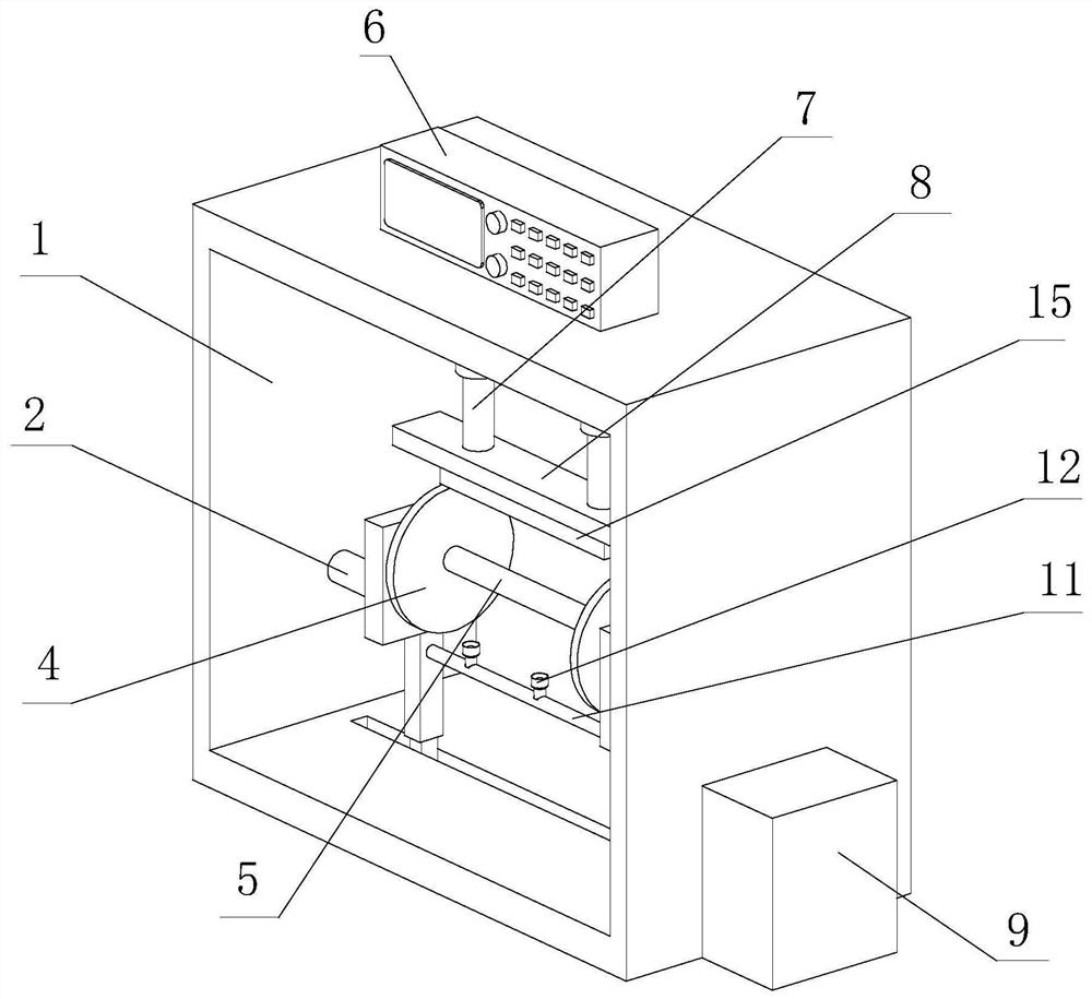
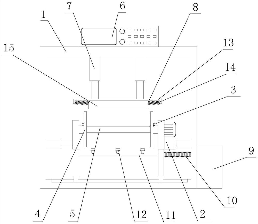
[0030] see Figure 1-5, the present invention provides a technical solution: a mechanical winding device for textile technology, including a main body 1, a moving winding device 2 and a dismounting device 3, the inner wall of the main body 1 is fixedly connected with a moving winding device 2, the moving winding One side of the wire device 2 is provided with a dismantling device 3, and one side of the mobile winding device 2 is fixedly installed with two reels 4 through the dismantling device 3, and one side of the reels 4 is fixedly connected with a winding column 5, and the main body The top outer wall of 1 is fixedly connected with the control cabinet 6, the top inner wall of the main body 1 is fixedly connected with the lifting cylinder 7, the bottom of the lifting cylinder 7 is fixedly connected with the moving plate 8, and the right outer wall of the main body 1 is fixedly connected with the fan dust removal box 9, the fan One side of the dust removal box 9 is fixedly co...

Embodiment 2

[0033] see Figure 1-Figure 7 As shown, on the basis of Embodiment 1, the present invention provides a technical solution downwards: the dismounting device 3 includes a connecting seat 301, the top of the connecting seat 301 is provided with a clamping groove 302, and both sides of the clamping groove 302 are provided with The accommodation groove 303, the inner wall of the accommodation groove 303 is fixedly connected with a reset spring 304, the side of the reset spring 304 away from the accommodation groove 303 is fixedly connected with a reset block 305, and the side of the winding reel 4 away from the winding post 5 is fixedly connected with a clamp block 306, the top of the clamping block 306 is provided with a rotating block 307, the bottom of the rotating block 307 is fixedly connected with a rotating rod 308, the inside of the clamping block 306 is provided with a moving through hole 309, and the outer wall of the rotating rod 308 is provided with a trapezoidal groove ...

Embodiment 3

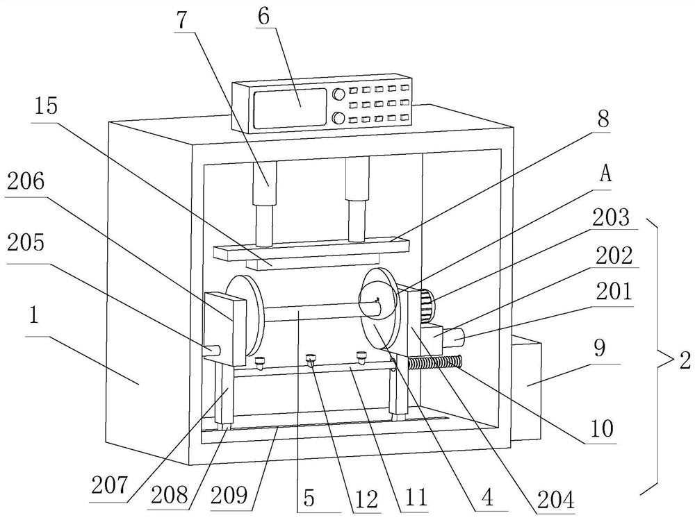
[0036] see Figure 1-Figure 3 As shown, on the basis of Embodiment 1 and Embodiment 2, the present invention provides a technical solution: the mobile winding device 2 includes a right hydraulic cylinder 201, and one side of the right hydraulic cylinder 201 is fixedly connected with a fixed connecting plate 202 , the top of the fixed connection plate 202 is fixedly connected with the driving motor 203, the side of the fixed connection plate 202 far away from the right hydraulic cylinder 201 is fixedly connected with the right connection plate 204, and the inner wall of one side of the main body 1 is fixedly connected with the left hydraulic cylinder 205, the left hydraulic cylinder The side of the cylinder 205 away from the inner wall of the main body 1 is fixedly connected with a left connecting plate 206, and the bottoms of the left connecting plate 206 and the right connecting plate 204 are respectively fixedly connected with a connecting column 207, and the bottom of the co...


PUM


Abstract

The invention discloses a mechanical winding device for textile technology, which comprises a main body, a moving winding device and a dismounting device, the inner wall of the main body is fixedly connected with a moving winding device, and one side of the moving winding device is arranged There is a dismantling device, and two reels are fixedly installed on one side of the mobile winding device through the dismantling device. Through the setting of the disassembly device, it is convenient to replace the winding reel, so that it is convenient to take the coil after winding, manually move the rotating block to the side away from the clamping block, the rotating rod moves at the same time, the trapezoidal groove gradually moves, and the reset block Sliding on the inner wall of the trapezoidal groove, when the reset block slides along the inner wall of the trapezoidal groove, it gradually moves to both sides of the rotating rod. One side of the seat moves, the embedded block and the embedded groove are separated from each other, and can be disassembled, so as to realize the function of quick replacement of the winding reel, facilitate the disassembly and maintenance of the winding reel, and improve the working efficiency.

Description

technical field [0001] The invention belongs to the technical field of winding devices, and in particular relates to a mechanical winding device for textile technology. Background technique [0002] Textile machine, also known as textile machine, loom, cotton spinning machine, etc., the ancient textile machine is a loom driven by manpower. The textile machine is the full name of the tool that processes raw materials such as thread, silk, and hemp into silk and then weaves them into cloth. Such as spinning pendants, spinning wheels, spindles, pedal looms, mechanical looms, modern CNC automatic looms, etc. The quality of textile gauze not only depends on the performance of textile machines, but also has high requirements for textile yarn raw materials. At present, most of the yarn winding machines use manual winding, the winding efficiency is not high and time-consuming and labor-intensive, some winding devices are used, the yarn is not evenly wound on the winding column, and ...

Claims


Application Information

Patent Timeline
Patent Type & Authority Patents(China)
IPC IPC(8): B65H54/553B65H54/28B65H54/38
CPCB65H54/553B65H54/2803B65H54/38B65H2701/31
Inventor 华东栋
Owner 泰安岱银新宇纺织有限公司
Why Eureka
Try Eureka