Equipment with quick take-up function for cable

A fast, functional technology for the delivery of filamentous materials, thin material handling, transportation and packaging, which can solve problems such as inconvenient cable cutting

Inactive Publication Date: 2021-02-05
江西万上实业有限公司
View PDF1 Cites 7 Cited by
  • Summary
  • Abstract
  • Description
  • Claims
  • Application Information

AI Technical Summary

Problems solved by technology

[0005] In order to overcome the inconvenient cutting of the finished cable when the cable is rolled, the technical problem of the present invention is to provide a fast winding cable that can be cut by itself. Equipment with fast take-up function for cables

Method used


Image

  • Equipment with quick take-up function for cable
  • Equipment with quick take-up function for cable
  • Equipment with quick take-up function for cable

Examples


Embodiment 1

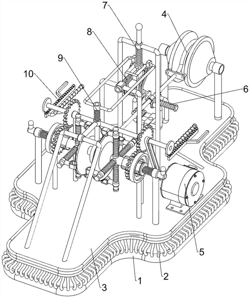
[0068] A device with a fast take-up function for cables, such as figure 1 As shown, it includes a first support frame 1, a second support frame 2, a base plate 3, a winding mechanism 4 and an automatic rotation mechanism 5, the first support frame 1 is provided with a second support frame 2, and the second support frame 2 is A base plate 3 is provided, and a wire winding mechanism 4 is arranged on the base plate 3 , and an automatic rotation mechanism 5 is arranged between the base plate 3 and the wire winding mechanism 4 .

[0069] When people need to take up the cable, people clamp the cable reel through the winding mechanism 4, and place the cable that needs to be wound on the winding mechanism 4, and at the same time, people wrap the cable at one end around the winding mechanism 4. On the reel, when people surround the cable at one end on the cable reel, people will turn on the automatic rotation mechanism 5, so that the automatic rotation mechanism 5 drives the winding me...

Embodiment 2

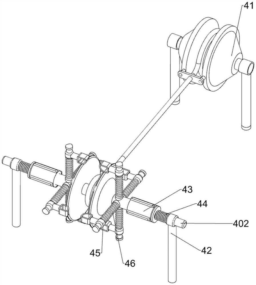
[0071] On the basis of Example 1, such as figure 2 As shown, the winding mechanism 4 includes a winding wheel 41, a first sliding support rod 42, a rotating connecting rod 402, a connecting column 43, a first spring 44, a sliding clamping block 45 and a second spring 46. The side rotation type is provided with a reel 41, the bottom plate 3 is provided with a first sliding support rod 42 on the front and rear sides of the upper middle part, and the two first sliding support rods 42 are all rotatably provided with a rotating connecting rod 402, and the rotating connecting rod 402 Connecting columns 43 are arranged on the top, and first springs 44 are sleeved inside the two rotating connecting rods 402. Both ends of the first spring 44 are respectively connected with the first sliding support rod 42 and connecting columns 43. The sliding clamping block 45 is provided in the uniform sliding type, and the second spring 46 is sleeved on the two sliding clamping blocks 45 , and the ...

Embodiment 3

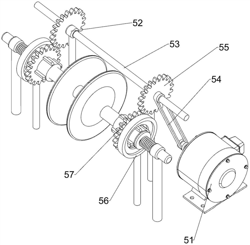
[0074] On the basis of Example 2, such as figure 1 , image 3 , Figure 4 , Figure 5 , Image 6 , Figure 7 and Figure 8 As shown, the automatic rotation mechanism 5 includes a motor 51, a rotating support rod 52, a rotating shaft 53, a transmission assembly 54, a first spur gear 55, a rotating connecting plate 56 and a second spur gear 57, and the front side of the upper middle part of the bottom plate 3 is equipped with a motor 51, the bottom plate 3 is equipped with a rotating support rod 52 on the front and rear sides of the upper middle part, and a rotating shaft 53 is arranged between the two rotating supporting rods 52, and a transmission assembly 54 is arranged between the rotating shaft 53 and the output shaft of the motor 51, and the rotating shaft 53 Both front and back sides are all provided with the first straight gear 55, are all provided with the rotating connecting disc 56 on the two connecting posts 43, are all provided with the second spur gear 57 on t...


PUM


Abstract

The invention relates to equipment with a take-up function, in particular to equipment with a quick take-up function for a cable. According to the equipment with the quick take-up function for the cable, the cable can be rapidly taken up, and the cable can be automatically cut off. The equipment with the rapid take-up function for the cable comprises a first supporting frame, a second supporting frame, a bottom plate, a coiling mechanism and an automatic rotating mechanism. The first supporting frame is provided with the second supporting frame. The bottom plate is arranged on the second supporting frame. The coiling mechanism is arranged on the bottom plate. The automatic rotating mechanism is arranged between the bottom plate and the coiling mechanism. According to the equipment with thequick take-up function for the cable, through mutual cooperation of the coiling mechanism and the automatic rotating mechanism, a motor is started, a rotating connecting rod automatically rotates, acable reel automatically rotates, accordingly, the cable is automatically wound, the effect of rapidly and automatically winding the cable is achieved, and through arrangement of a clamping mechanism,the cable is guided through a clamping rod.

Description

technical field [0001] The invention relates to a device with a wire-receiving function, in particular to a device with a fast wire-receiving function for cables. Background technique [0002] When people complete the work on the construction site, they need to reel up the cables used to prevent people from tripping and other accidents while walking. However, there are many cables used in the construction site, so people manually rewind the cables. The process takes too long and is more time-consuming and labor-intensive than the staff on the construction site. [0003] Patent application: CN201621355900.9, the publication date is 20161210, which discloses a cable winding machine, which includes a frame, a wire inlet end, a slideway, a slider, a tension wheel, a speed sensor, a slide bar, a slide rail and Fixed pulley and other parts, the cable is wound around the first wire roller and the second wire roller in turn, after the adjustment and straightening of the two wire ro...

Claims


Application Information

Patent Timeline
Patent Type & Authority Applications(China)
IPC IPC(8): B65H54/553B65H54/44B65H54/30B65H54/70B21F11/00
CPCB21F11/00B65H54/30B65H54/44B65H54/553B65H54/70B65H2701/34
Inventor 黄凤民
Owner 江西万上实业有限公司
Why Eureka
Try Eureka