Installation system and construction method of steel arch bridge with upper span channel

A construction method and technology for steel arch bridges, applied in the direction of bridges, bridge construction, erection/assembly of bridges, etc., can solve the problems of difficult to solve the connection between segments, difficult to implement construction, etc., to reduce difficulty, reduce installation difficulty, and improve stress performance effect

Active Publication Date: 2022-03-25
ANHUI HIGHWAY ENG CORP
View PDF0 Cites 0 Cited by
  • Summary
  • Abstract
  • Description
  • Claims
  • Application Information

AI Technical Summary

Problems solved by technology

[0003] In the prior art, there is a floating towing installation process for long-span steel structure arch bridges. The steel structure arch bridge includes several steel bridge components manufactured in sections, and the overall pre-assembly is carried out in the factory according to the assembly state on site; On the river bank of the site, the steel bridge components were assembled according to the assembly area, which included two steel trusses and two bridge deck blocks; the two steel trusses were floated and hoisted to the pier respectively, and the assembled One bridge deck block is hoisted directly between the two steel trusses, and the other bridge deck block is first transported to the opposite bank by barge, and then hoisted between the two steel trusses by the second crawler, and the bridge deck block is connected to the steel truss in sections. Assembly and welding to complete the assembly of the entire steel bridge; although this technology can reduce the impact of construction on navigation to a certain extent, when the stability of the construction structure is poor and the water flow is not stable, the construction is difficult to implement; and this technology is difficult to solve Connection problems between segments

Method used


Image

  • Installation system and construction method of steel arch bridge with upper span channel
  • Installation system and construction method of steel arch bridge with upper span channel
  • Installation system and construction method of steel arch bridge with upper span channel

Examples


Embodiment Construction

[0038] In order to make the purpose, technical solution and advantages of the present application clearer, the present application will be further described in detail below in conjunction with the accompanying drawings and embodiments. It should be understood that the specific embodiments described here are only used to explain the present application, and are not intended to limit the present application. Based on the examples in this application, all other examples obtained by persons of ordinary skill in the art without making creative efforts belong to the scope of protection of this application.

[0039] It should be understood by those skilled in the art that the technical terms or scientific terms used in the claims and the description shall have the ordinary meanings understood by those with ordinary skills in the technical field to which this application belongs. Words such as "connect" or "connected" are not limited to physical or mechanical connections, but may incl...


PUM


Abstract

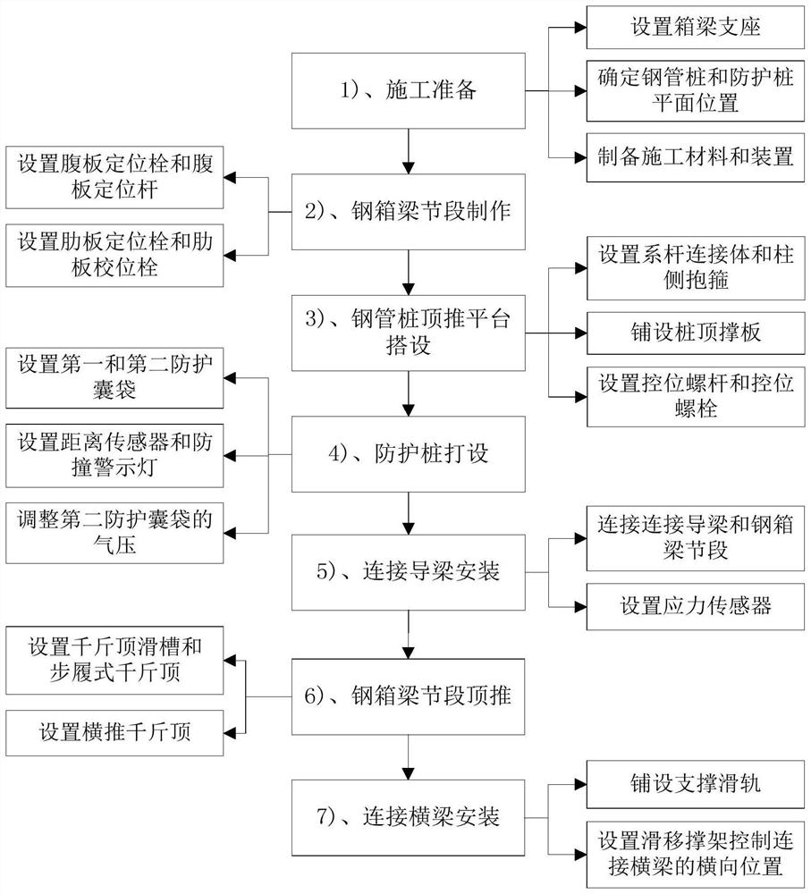
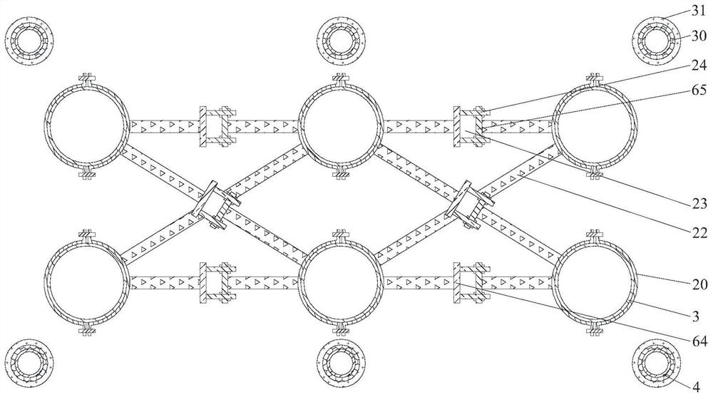
The present invention relates to the field of bridge engineering, and more specifically relates to an installation system and a construction method of an upper-span channel steel arch bridge; including the following construction steps: 1) construction preparation, 2) fabrication of steel box girder segments, 3) erection of a steel pipe pile jacking platform , 4) Protective pile driving, 5) Connecting guide beam installation, 6) Steel box girder section pushing, 7) Connecting beam installation, the web positioning bolt and web positioning rod are used to limit the width of the box girder web during construction. position, the position of the box girder ribs is defined by the rib positioning bolts and the rib alignment bolts, the adjacent steel pipe piles are connected into a whole by the tie rod connector and the pile side hoop, and the The connection guide beam and the steel box girder section are connected as a whole, and the supporting slide rail is laid on the steel box girder section, and the lateral position of the connecting beam can be controlled by the sliding brace. The invention improves the installation construction of the long-span steel arch bridge Quality and efficiency, reducing the difficulty of jacking construction.

Description

technical field [0001] The invention relates to the field of bridge engineering, and more particularly relates to an installation system and a construction method of an upper-span channel steel arch bridge. Background technique [0002] The construction scale of large-span municipal steel arch bridges has gradually increased, which has brought many conveniences to the emergence of people; however, with the increase of the span of municipal steel arch bridges, bridge design, construction, manufacturing and other processes will affect the overall quality of steel arch bridges. In this case, it is particularly important to strengthen the control and management of the steel arch bridge construction process. [0003] In the prior art, there is a floating towing installation process for long-span steel structure arch bridges. The steel structure arch bridge includes several steel bridge components manufactured in sections, and the overall pre-assembly is carried out in the factory...

Claims


Application Information

Patent Timeline
Patent Type & Authority Patents(China)
IPC IPC(8): E01D21/00E01D21/06
CPCE01D21/00E01D21/06
Inventor 陈明洋宣菲金礼强万韦吴德胜周树标赵军飞陈磊丁爱平马玉赞荣信
Owner ANHUI HIGHWAY ENG CORP
Why Eureka
Try Eureka