Automatic water cooler circulating water control device

A technology for control devices and water coolers, applied in cooling fluid circulation devices, household refrigeration devices, lighting and heating equipment, etc., which can solve the problems of short contact time between circulating water and heat transfer medium, unfavorable cooling work of water coolers, high loss of refrigeration systems, etc. problems, to achieve the effect of improving convenience, increasing service life and reducing loss

Inactive Publication Date: 2021-02-05
西安致开工业自动化工程有限公司
View PDF3 Cites 2 Cited by
  • Summary
  • Abstract
  • Description
  • Claims
  • Application Information

AI Technical Summary

Problems solved by technology

[0009] The purpose of the present invention is to solve the problem in the prior art that the contact time between the circulating water and the heat exchange medium is too short, resulting in poor w...

Method used


Image

  • Automatic water cooler circulating water control device
  • Automatic water cooler circulating water control device

Examples


Embodiment 1

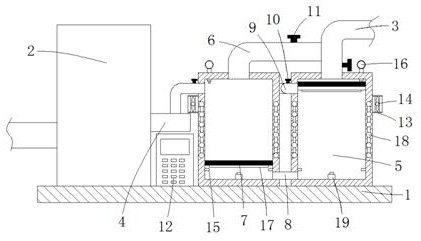
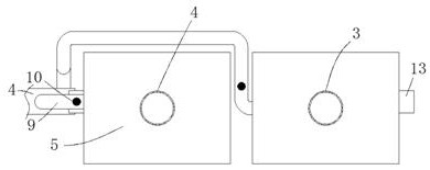
[0025] Example 1 as Figure 1-2 As shown, the automatic water-cooler circulating water control device includes a base plate 1 and a water-cooler body 2. The lower end of the water-cooler body 2 is fixedly connected to the left side of the upper end of the base plate 1, and the output end and input end of the water-cooler body 2 are respectively fixed. The water inlet main pipe 3 and the return pipe 4 are connected. Two water storage tanks 5 are arranged on the right side of the water cooler body 2, and the lower ends of the two water storage tanks 5 are fixedly connected with the upper end of the bottom plate 1. The water inlet main pipe 3 is far away from the water cooling One end of the machine body 2 is fixedly connected to the upper end of one of the water storage tanks 5, and the end of the pipe wall of the water inlet main pipe 3 away from the water cooler body 2 is fixedly connected with a water inlet auxiliary pipe 6, and the water inlet auxiliary pipe 6 is far away fro...

Embodiment 7

[0031] Example 7 as Figure 1-2As shown, this automatic water-cooler circulating water control device includes a base plate 1 and a water-cooler body 2. It is characterized in that the lower end of the water-cooler body 2 is fixedly connected to the left side of the upper end of the base plate 1, and the output end of the water-cooler body 2 The water inlet main pipe 3 and the return pipe 4 are respectively fixedly connected to the input end, and two water storage tanks 5 are arranged on the right side of the water cooler body 2, and the lower ends of the two water storage tanks 5 are fixedly connected with the upper end of the bottom plate 1, and the water inlet The end of the main pipe 3 far away from the water cooler body 2 is fixedly connected to the upper end of one of the water storage tanks 5, and the end of the pipe wall of the water inlet main pipe 3 away from the water cooler body 2 is fixedly connected with a water inlet secondary pipe 6, and the water inlet secondar...


PUM


Abstract

The invention relates to the technical field of water coolers, and discloses an automatic water cooler circulating water control device which comprises a bottom plate and a water cooler body. The lower end of the water cooler body is fixedly connected with the left side of the upper end of the bottom plate; the output end and the input end of the water cooler body are fixedly connected with a mainwater inlet pipe and a return pipe correspondingly; two water storage tanks are arranged on the right side of the water cooler body; the lower ends of the two water storage tanks are fixedly connected with the upper end of the bottom plate; the end, away from the water cooler body, of the main water inlet pipe is fixedly connected with the upper end of one water storage tank; the end, away from the water cooler body, of the pipe wall of the main water inlet pipe is fixedly connected with an auxiliary water inlet pipe; the end, away from the main water inlet pipe, of the auxiliary water inletpipe is fixedly connected with the upper end of the other water storage tank; and piston plates are slidably connected into the two water storage tanks. According to the automatic water cooler circulating water control device provided by the invention, a refrigerating effect cannot be affected due to too high heat of returned water, high loss of a refrigerating system cannot be caused, the servicelife of the water cooler body is prolonged, meanwhile, a heat dissipation effect on the returned water is good, control automation is achieved, and convenience in use is realized.

Description

technical field [0001] The invention relates to the technical field of water coolers, in particular to an automatic water cooler circulating water control device. Background technique [0002] Water chiller, also known as chiller, is a cooling water device that can provide constant temperature, constant flow, and constant pressure. Water chillers are divided into two types: air-cooled chillers and water-type chillers. [0003] After retrieval, Chinese Patent Publication No. CN202677178U discloses a circulating water control device for a water cooler, including a controller, a circulating water pump, a pressure sensor, a temperature sensor and a frequency converter. The controller is electrically connected to the pressure sensor, and the controller and The frequency converter is electrically connected, the frequency converter is electrically connected to the circulating water pump, and the temperature sensor is electrically connected to the controller; [0004] After retriev...

Claims


Application Information

Patent Timeline
IPC IPC(8): F25D31/00F25D17/02F25D29/00
CPCF25D17/02F25D29/001F25D31/00
Inventor 勾薇
Owner 西安致开工业自动化工程有限公司
Why Eureka
Try Eureka