Coating defect detection and marking system and method

A defect detection and marking system technology, used in optical testing of flaws/defects, measuring devices, material analysis by optical means, etc., can solve the problems of low coating defect detection efficiency and inability to mark defect types.

Pending Publication Date: 2021-02-05
HARBIN ENG UNIV
View PDF8 Cites 7 Cited by
  • Summary
  • Abstract
  • Description
  • Claims
  • Application Information

AI Technical Summary

Problems solved by technology

[0005] Based on this, the present invention proposes a coating defect detection and marking system. The coating defect detection and marking system based on machine vision aims to solve the current technical problems of low efficiency of coating defect detection and inability to mark defect types

Method used


Image

  • Coating defect detection and marking system and method
  • Coating defect detection and marking system and method
  • Coating defect detection and marking system and method

Examples


Embodiment Construction

[0038] The present invention will be further described in detail below in conjunction with the accompanying drawings and specific embodiments.

[0039] In order to make the above objects, features and advantages of the present invention more comprehensible, specific implementations of the present invention will be described in detail below in conjunction with the accompanying drawings. Specific details are set forth in the following description in order to fully demonstrate the features and advantages of the invention. However, the present invention can be implemented in many other ways different from those described here, and those skilled in the art can make similar improvements without departing from the connotation of the present invention, so the present invention is not limited by the specific implementations disclosed below.

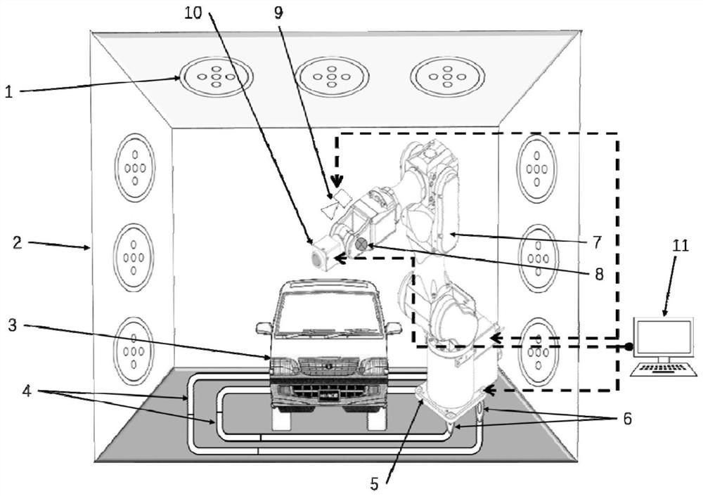
[0040] see figure 1 and 3, the invention discloses a coating defect detection and marking system, the coating defect detection and marking syst...


PUM


Abstract

The invention provides a coating defect detection and marking system and method, which relate to an image acquisition and processing technology, belong to the technical field of nondestructive testing, and are used for detecting coating defects on the surface of an automobile body and marking the defects. The coating defect detection and marking system comprises a lighting device 1, a detection workshop bracket 2, a to-be-detected vehicle body 3, a track 4, a supporting base 5, a track moving device 6, a mechanical arm 7, a lighting source 8, a defect marking device 9, an image acquisition device 10 and a computer system 11. Defect detection can be carried out on the coating on the surface of the whole vehicle, coating defects are classified, defect marking is carried out with a solution with a specific color, and automatic and assembly line detection is carried out on the coating defects.

Description

technical field [0001] The invention relates to image acquisition and processing technology, belongs to the technical field of non-destructive testing, in particular to a coating defect detection and marking system. Background technique [0002] Non-destructive testing refers to the use of heat, sound and light caused by structural abnormalities or defects inside the material without damaging or affecting the performance of the tested object, and without damaging the internal tissue or external surface morphology of the tested object. Changes in reactions such as electricity, magnetism, etc., by means of physical or chemical methods, with the help of modern technology and equipment, the structure, nature, state and type, nature, quantity, shape, location, Methods of inspection and testing of dimensions, distribution and variations thereof. Optical imaging technology captures the light information reflected by the target to form the target image information in the sensor, wh...

Claims


Application Information

Patent Timeline
Patent Type & Authority Applications(China)
IPC IPC(8): G01N21/88G01N21/84G01N21/01B05B3/02
CPCG01N21/8851G01N21/8422G01N21/01B05B3/02G01N2021/8427G01N2021/888G01N2021/8854G01N2021/8887G01N2021/0181
Inventor 赵辉吕永胜王向伟彭锐晖沙建军陈宗阳赵博张公韬仇吉业
Owner HARBIN ENG UNIV
Why Eureka
Try Eureka