
Method for non-destructive testing of millimeter wave BGA packaging assembly

A technology of packaging components and non-destructive testing, which is applied in the microwave field to achieve the effects of improved reliability, simple structure, and high design flexibility

Active Publication Date: 2019-04-19
10TH RES INST OF CETC
View PDF8 Cites 3 Cited by
  • Summary
  • Abstract
  • Description
  • Claims
  • Application Information

AI Technical Summary

Problems solved by technology

[0005] The purpose of the present invention is to provide a non-destructive testing method that is easy to disassemble, high in flexibility, low in cost, and has no secondary damage to the tested BGA package component in view of the deficiencies in the existing millimeter-wave BGA package component test method.

Method used


Image

  • Method for non-destructive testing of millimeter wave BGA packaging assembly
  • Method for non-destructive testing of millimeter wave BGA packaging assembly
  • Method for non-destructive testing of millimeter wave BGA packaging assembly

Examples


Embodiment Construction

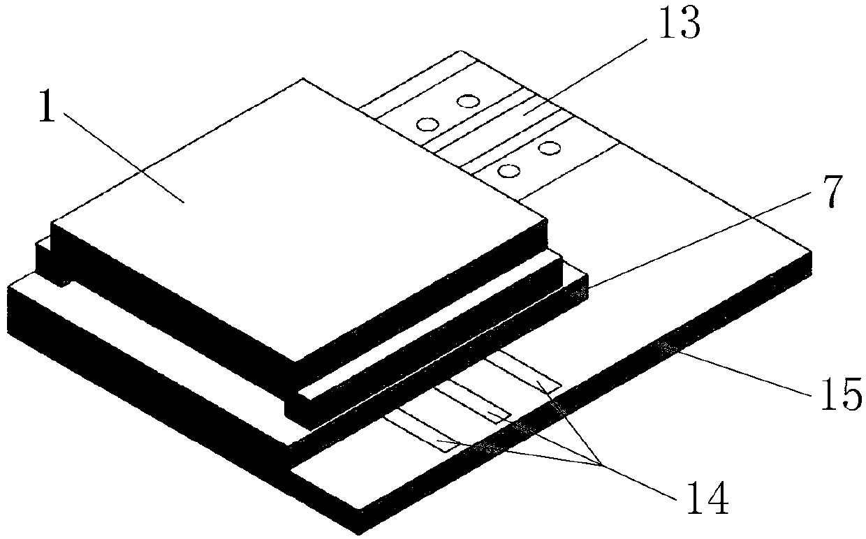
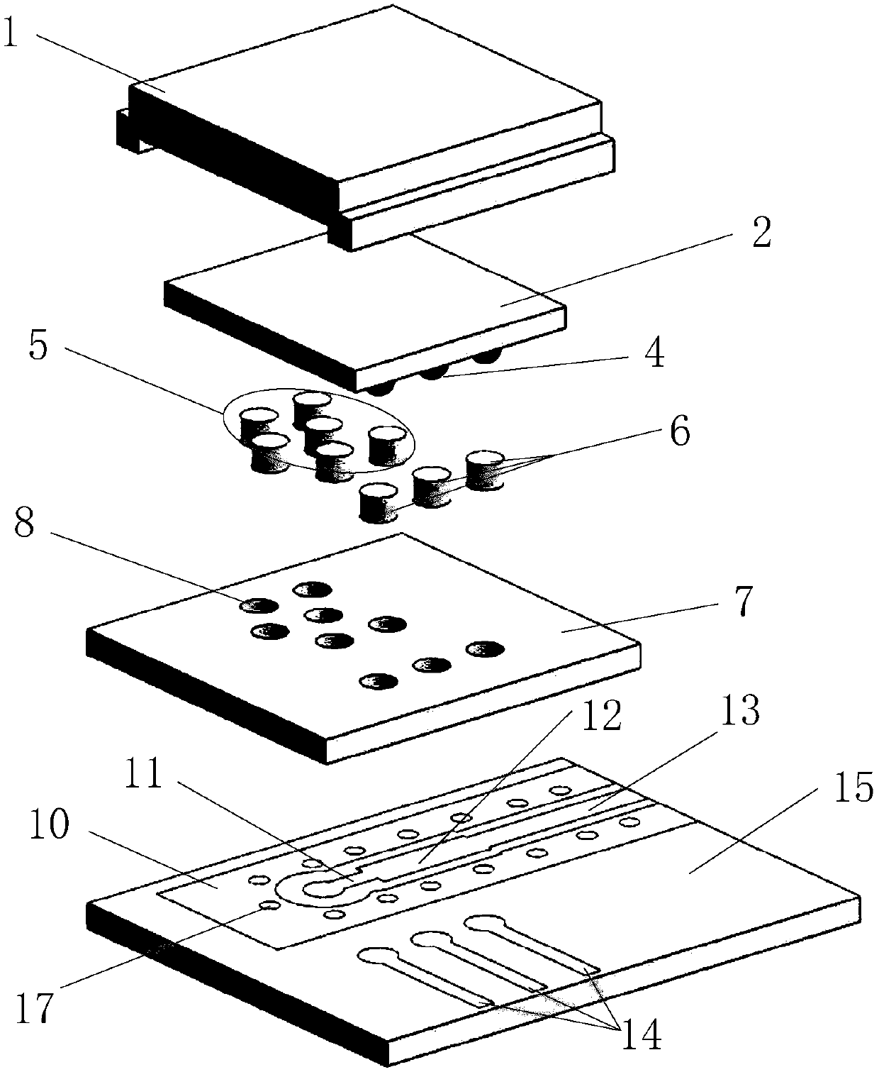
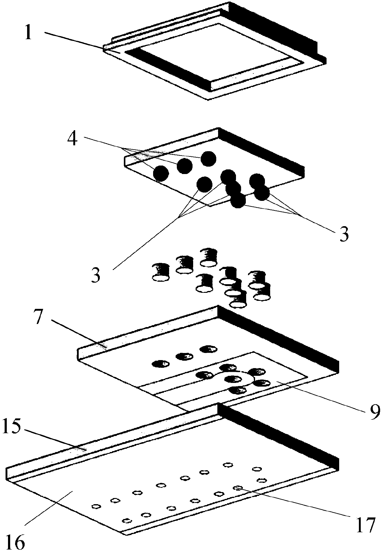
[0017] refer to Figure 1-Figure 3 . According to the present invention, on the front copper-clad surface of the second dielectric substrate 15, a ground copper surface 10 corresponding upward to the high-frequency solder ball 3 on the BGA package assembly 2 and a band circle orthogonal to it and corresponding to the low-frequency solder ball 4 are etched. The finger-shaped low-frequency transfer line 14 of the chip, and the high-impedance matching line 11 with a disc and the low-impedance matching line 12 connected to its extension are made on the long direction of the ground copper surface 10, and the low-impedance matching line 12 is connected with the low-impedance The coplanar transmission line 13 connected to the terminal of the matching line 12, the back of the second dielectric substrate 15 is covered with copper to form a large-area lower ground copper surface 16, and the ground copper surface 10 and the large-area lower ground copper surface are connected by U-shaped...


PUM


Abstract

The invention discloses a method for non-destructive testing of a millimeter wave BGA packaging assembly, and aims to provide a non-destructive testing method which is easy for disassembly and assembly, high in flexibility and free of secondary damage to a tested BGA packaging assembly. In a testing process, a tested BGA packaging assembly (2) is reversely placed on a first dielectric substrate (7) through a metal box body (1), and a welding ball of the BGA packaging assembly (2) makes elastic contact with a high-frequency fuzz button (5) and a low-frequency fuzz button (6). The low-frequencyfuzz button (6) is in contact with a wafer of the low-frequency adaptor cord (14) and is communicated with a low-frequency test interface formed by the finger line. A high-frequency signal is vertically transited to a high impedance matching line (11) through the high-frequency fuzz button (5) and is transmitted to a coplanar transmission line (13) through a low impedance matching line (12) to form a standard 50-ohm universal high-frequency test interface. The performance of the BGA packaging assembly (2) can be nondestructively tested through the coplanar line (13) and the low-frequency adaptor line (14).

Description

technical field [0001] The invention belongs to the field of microwave technology, in particular to a method for testing the performance of a millimeter-wave BGA packaging component. Background technique [0002] In recent years, the continuous improvement of the performance of millimeter wave devices and the continuous reduction of cost have effectively promoted the application of millimeter waves in various fields. With the improvement of millimeter-wave circuit integration, ball grid array BGA (Ball Grid Array Package) packaging, which has high-density high-low frequency I / O interfaces and is suitable for large-scale SMT assembly processes, has become a mainstream packaging technology. The BGA ball grid array package is to make an array of solder balls on the bottom of the package substrate as the I / O terminal of the circuit and interconnect the printed circuit board (PCB). The device packaged by this technology is a surface-mount device, which can realize high-density a...

Claims


Application Information

Patent Timeline
Patent Type & Authority Applications(China)
IPC IPC(8): G01R31/28
CPCG01R31/2818
Inventor 刘帅张凯
Owner 10TH RES INST OF CETC
Learn More