
Resonant transformer

A resonant transformer and magnetic core technology, which is applied in the field of resonant transformers, can solve the problems of large leakage inductance between primary coil and secondary coil, complex overall structure of resonant transformer, and restriction of power supply efficiency, so as to reduce electromagnetic interference, ensure safety and The effect of reliability and enhanced coupling

Pending Publication Date: 2021-02-05
衡山萌泰电子有限公司
View PDF17 Cites 1 Cited by
  • Summary
  • Abstract
  • Description
  • Claims
  • Application Information

AI Technical Summary

Problems solved by technology

[0003] With the development of electronic circuits and switching power supplies in the direction of high frequency, high power, high reliability, and high integration, and the continuous reduction of the size of high-speed ultra-large-scale integrated circuits, users have put forward higher requirements for the performance of DC power supplies , in order to design a high-power DC switching power supply that meets the requirements, the method of using an LLC resonant transformer in the switching power supply is generally adopted, but the overall structure of the existing resonant transformer is complex, and the leakage inductance between the primary coil and the secondary coil is large , leading to a large loss in the resonant transformer, which seriously restricts the improvement of the power supply efficiency

Method used


Image

  • Resonant transformer
  • Resonant transformer
  • Resonant transformer

Examples


Embodiment 1

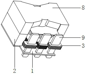
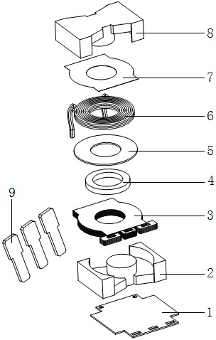
[0030] Example 1: Combining Figure 1 ~ Figure 4As shown, the primary coil in the present invention is composed of double-layer winding cakes reversely stacked, and each layer of winding cakes is made of multi-strand self-adhesive three-layer insulating wires. There are a total of 14 turns around the cake and work in parallel. The secondary coil is composed of 8 overlapping copper sheets. The thickness of each copper sheet is 0.5mm, and an insulating plate is provided between adjacent copper sheets. Adhesive tape, the thickness of the insulating plate is 0.05mm, the thickness of the spacer between the corresponding magnetic core center columns of the primary coil and the secondary coil is 5mm, and the three secondary pins are made of copper plates with a thickness of 2mm At the same time, the surface of the three secondary pins is electroplated with matte tin, which not only facilitates the insertion and welding of the secondary pins, but also increases the conductivity of eac...


PUM

PropertyMeasurementUnit
Thicknessaaaaaaaaaa

Abstract

The invention provides a resonant transformer, which comprises a first magnetic core, a second magnetic core, a secondary coil, a primary coil, a spacer and a bottom plate, and is characterized in that the first magnetic core is fixedly arranged on the bottom plate, the second magnetic core is arranged at the top end of the first magnetic core, and the secondary coil is wound on a central column of the first magnetic core; the primary coil is wound on the central column of the second magnetic core, the spacers are arranged between the secondary coil and the primary coil and between the secondary coil and the corresponding central column of the magnetic core, and the secondary coil comprises three secondary pins. A double-layer winding cake reverse lap winding structure formed by winding aplurality of strands of self-adhesive three-layer insulated wires is adopted as the primary coil, and the secondary coil is formed by overlapping a plurality of copper sheets, so that the leakage inductance between the primary coil and the secondary coil can be effectively reduced, the loss of the resonant transformer is reduced, and the working efficiency of the power supply is improved; meanwhile, the overall structure is scientific, reasonable, simple, compact and convenient to install and operate. Theresonant transformer is widely suitable for switching power supply voltage transformationmatching use.

Description

technical field [0001] The invention relates to power supply equipment, in particular to a resonant transformer. Background technique [0002] Switch mode power supply is referred to as SMPS, also known as switching power supply and switching converter. Converted to the voltage or current required by the user end, the input of the switching power supply is mostly AC power, and the output is mostly DC power. [0003] With the development of electronic circuits and switching power supplies in the direction of high frequency, high power, high reliability, and high integration, and the continuous reduction of the size of high-speed ultra-large-scale integrated circuits, users have put forward higher requirements for the performance of DC power supplies , in order to design a high-power DC switching power supply that meets the requirements, the method of using an LLC resonant transformer in the switching power supply is generally adopted, but the overall structure of the existin...

Claims


Application Information

Patent Timeline
IPC IPC(8): H01F27/24H01F27/36H01F27/28H01F27/32H01F27/34
CPCH01F27/24H01F27/324H01F27/2823H01F27/2847H01F27/346
Inventor 成桂吉
Owner 衡山萌泰电子有限公司
Learn More