New energy battery pack convenient for space adjustment

A space adjustment and new energy technology, applied to battery components, batteries, circuits, etc., can solve the problems of insufficient overall stability, unstable positioning, affecting operation convenience and time-consuming, and achieve good anti-seismic protection effect , Convenient installation and subsequent disassembly, and the effect of convenient subsequent disassembly and assembly operations

Inactive Publication Date: 2021-02-05
冯学阳
View PDF0 Cites 0 Cited by
  • Summary
  • Abstract
  • Description
  • Claims
  • Application Information

AI Technical Summary

Problems solved by technology

[0007] The purpose of the present invention is to provide a new energy battery pack that is convenient for space adjustment to solve the above-mentioned background technology. For the existing new energy battery pack, it is easy to cause problems when positioning, clamping and reinforcing battery elements of different types and sizes. The difference and difference in the internal space cause the instability and looseness of its positioning. During long-term use, its overall stability is insufficient, and it is prone to displacement and impact caused by shaking, vibration and falling, which is not convenient for the positioning of battery components and the positioning of the battery pack. The overall reinforcement will affect the convenience and time-consuming of the operation when the battery components need to be disassembled for maintenance and replacement, and the anti-seismic protection performance of the reinforced and fixed battery components is not good. During the driving process of the vehicle, it is easy to appear one-sided direction The shaking on the battery causes the battery element to vibrate at a frequency, which affects its service life

Method used


Image

  • New energy battery pack convenient for space adjustment
  • New energy battery pack convenient for space adjustment
  • New energy battery pack convenient for space adjustment

Examples


Embodiment Construction

[0031] The following will clearly and completely describe the technical solutions in the embodiments of the present invention with reference to the accompanying drawings in the embodiments of the present invention. Obviously, the described embodiments are only some, not all, embodiments of the present invention. Based on the embodiments of the present invention, all other embodiments obtained by persons of ordinary skill in the art without making creative efforts belong to the protection scope of the present invention.

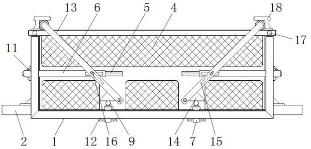
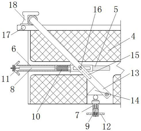
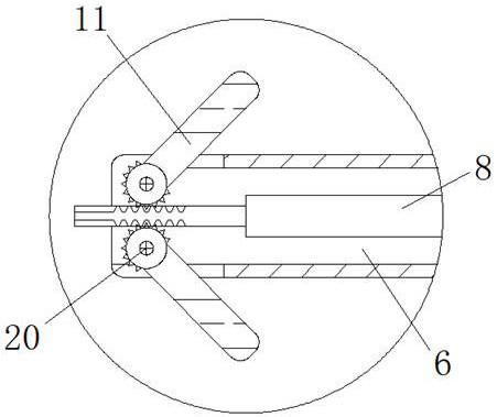
[0032] see Figure 1-9 , the present invention provides a technical solution: a new energy battery pack that is convenient for space adjustment, including a bottom outer frame 1, a fixing frame 2, a positioning mesh plate 3, an isolation frame 4, a first chute 5, and a first fixing bar 6 , the second fixing bar 7, the first positioning pin 8, the second positioning pin 9, the elastic member 10, the first side limit rod 11, the second side limit rod 12, the handl...


PUM


Abstract

The invention discloses a new energy battery pack convenient for space adjustment. The new energy battery pack comprises a bottom outer frame, a handle, a first pressing plate and a positioning strip,a fixing frame is fixedly installed at the bottom of the outer wall of the bottom outer frame, a positioning net plate is arranged in the middle of the bottom of the bottom outer frame, and an isolation frame is movably installed at the top of the bottom outer frame; and a first sliding groove is formed in the outer wall of the isolation frame, a first positioning bolt and a second positioning bolt are movably installed in the first fixing strip and the second fixing strip in a penetrating mode correspondingly, a first worm is rotatably installed in the edge of the top of the isolation frame,and an inner hollow plate is installed at the top of the isolation frame in an embedded mode. According to the new energy battery pack convenient for space adjustment, assembly positioning of the battery pack and adjustment and change of the internal space of the battery pack are facilitated, so that overall use positioning and subsequent disassembly and assembly operation are more convenient, and the new energy battery pack has a good use anti-seismic protection effect on internal batteries.

Description

technical field [0001] The invention relates to the related technical field of new energy battery packs, in particular to a new energy battery pack convenient for space adjustment. Background technique [0002] The new energy battery pack is an overall integration of electric energy storage and transfer, including battery components used for energy storage, outer protective shells and supporting electronic components, etc. Installation and positioning, preventing problems such as shaking and falling and heat accumulation during use, and providing the necessary working environment for the normal use of battery components are important components for the routine utilization of modern new energy. [0003] However, the existing new energy battery packs have the following problems in use: [0004] 1. For battery components used for energy storage of different sizes, when positioning, clamping and reinforcing, it is easy to cause unstable and loose positioning due to the differen...

Claims


Application Information

Patent Timeline
Patent Type & Authority Applications(China)
IPC IPC(8): H01M50/242H01M50/249H01M50/267H01M50/289
CPCH01M2220/20Y02E60/10
Inventor 冯学阳
Owner 冯学阳
Why Eureka
Try Eureka