Check patentability & draft patents in minutes with Patsnap Eureka AI!

A hanging rotary generator

A technology for generators and overhangs, which is applied in the direction of generators/motors, engines, wind power generation, etc. It can solve the problems that the online monitoring technology of wind turbine blades has not been widely used and cannot meet production needs, and achieves simple structure and excitation process , strong power generation and power supply capabilities, and reliable incentives

Active Publication Date: 2021-10-29
ZHEJIANG NORMAL UNIVERSITY
View PDF9 Cites 0 Cited by
  • Summary
  • Abstract
  • Description
  • Claims
  • Application Information

AI Technical Summary

Problems solved by technology

With the increasing length of wind turbine blades and the overall number of wind turbines, the previous method of relying on manual regular inspection and maintenance can no longer meet production needs
Therefore, various forms of wind turbine blade health status monitoring methods and corresponding power supply devices have been proposed. However, due to the constraints of existing power supply device reliability, power generation, and electromagnetic compatibility Monitoring technology is not yet widely used

Method used


Image

  • A hanging rotary generator
  • A hanging rotary generator
  • A hanging rotary generator

Examples


Embodiment Construction

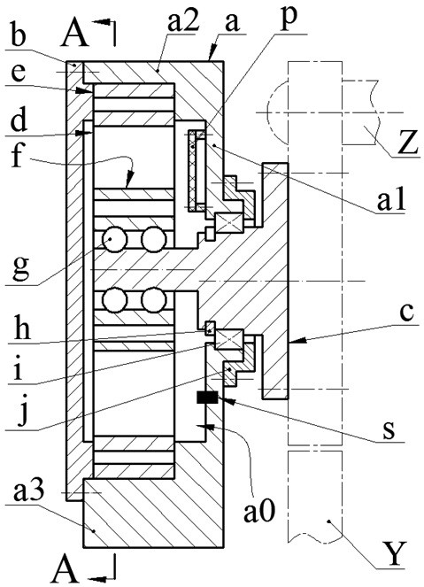
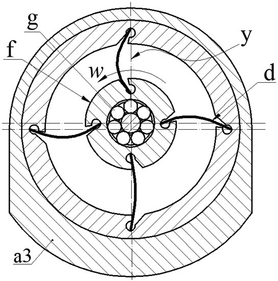
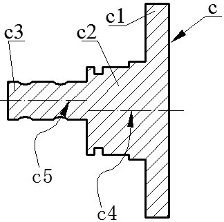
[0014] The rotary generator of the present invention consists of a main body a, an end cover b, a cantilever shaft c, a piezoelectric vibrator d, a fixed coil e, a moving coil f, a rolling body g, a retaining spring h, a bearing i, a bearing cover j, a sensor s and a circuit Plate p constitutes. The cantilever shaft c is provided with a left semi-axis c3, a right semi-axis c2 and a flange c1 from left to right. The left semi-axis c3 and the right semi-axis c are parallel but not coaxial; the flange c1 is installed on the wind turbine by screws The blade Y is installed on the main shaft Z of the generator; the main body a is provided with a body cavity a0, and the side wall a1 of the body cavity a0 is installed on the right half shaft c2 through the bearing i, the retaining spring h and the bearing cover j, and the side wall The circuit board p and sensor s are installed on a1; the left semi-axis c3 is placed inside the body cavity a0, and the moving coil f is sleeved on the le...


PUM


Abstract

The invention relates to a suspension type rotary generator, which belongs to the field of piezoelectric power generation. The cantilever shaft is provided with a left half shaft, a right half shaft and a flange in sequence from left to right. The flange is installed on the blade of the wind turbine, and the blade is installed on the main shaft of the generator; a body cavity is arranged on the main body, and the side wall of the body cavity The bearing is installed on the right half shaft, and the circuit board is installed on the side wall; the outer side of the cylinder wall of the body cavity is equipped with an inertia block, and the end is equipped with an end cover, and the end cover presses the fixed ring in the body cavity, the left and right half shafts are parallel, and the left A moving coil is set on the half shaft, and the moving coil is provided with a moving coil hole with a driving ring groove, and a fixed coil hole with a fixed coil groove is provided on the fixed ring; when the center of the fixed moving coil and the center of the fixed moving coil hole are collinear The intersection points of the extension line of the side wall of the ring groove and the concentric line are respectively located on the inner circumference of the moving and fixed ring hole, and the moving and fixed ring groove is located on the same side of the concentric line; one end of the piezoelectric vibrator leans against the inner wall of the fixed ring hole, and the other One end leans against the inner wall of the moving coil hole; when working, the left half shaft passes through the rolling body and the moving coil to force the piezoelectric vibrator to produce reciprocating bending deformation to generate electricity.

Description

technical field [0001] The invention belongs to the technical field of new energy and power generation, and in particular relates to a hanging rotary generator used for power supply of a blade monitoring system of a large wind power generator. Background technique [0002] The blade is the key component of the wind turbine to receive wind energy and convert it into kinetic energy, which determines the reliability and service life of the generator. Because blades usually work in harsh environments, and their own structural scale, weight and working load are very large, in addition to being damaged by irresistible natural disasters such as lightning strikes and earthquakes, damage to blades caused by natural corrosion, wear and fatigue stress, etc. It is also inevitable. Practice has shown that one-third of the accidents during the operation of wind turbines are caused by blade damage, so the health monitoring of wind turbine blades is imperative. With the increasing length ...

Claims


Application Information

Patent Timeline
Patent Type & Authority Patents(China)
IPC IPC(8): H02N2/18F03D9/25F03D80/00
CPCF03D9/25F03D80/00H02N2/185Y02E10/72
Inventor 蒋永华柴君凌刘盼盼赖德章祝孟松王淑云阚君武曾平
Owner ZHEJIANG NORMAL UNIVERSITY
Features
  • R&D
  • Intellectual Property
  • Life Sciences
  • Materials
  • Tech Scout
  • Unparalleled Data Quality
  • Higher Quality Content
  • 60% Fewer Hallucinations
Learn More