Vibration damper of airborne crystal oscillator

A technology of vibration damping device and crystal oscillator, which is applied in the direction of electrical components, impedance networks, etc., can solve the problems of large fluctuations in vibration damping performance with temperature changes, difficulty in making the natural frequency of the vibration damping structure low, and reducing the low frequency anti-vibration performance of the crystal oscillator. Achieve the effects of light weight, low device cost and high vibration isolation efficiency

Pending Publication Date: 2021-02-05
CHINA ELECTRONICS TECH GRP NO 26 RES INST
View PDF0 Cites 2 Cited by
  • Summary
  • Abstract
  • Description
  • Claims
  • Application Information

AI Technical Summary

Problems solved by technology

This vibration damping method is simple in structure and has a certain vibration damping effect, but due to the narrow temperature range of the rubber, the vibration damping performance fluctuates greatly with temperature changes, and there is a risk of falling off in the pasted installation, and the reliability is low; while installing rubber vibration damping It is difficult to lower the natural frequency of the vibration-damping structure of the crystal oscillator. The natural frequency is generally around 200Hz, which reduces the low-frequency anti-vibration performance of the crystal oscillator.

Method used


Image

  • Vibration damper of airborne crystal oscillator
  • Vibration damper of airborne crystal oscillator
  • Vibration damper of airborne crystal oscillator

Examples


Embodiment Construction

[0022] The present invention will be further described in detail below in conjunction with the accompanying drawings.

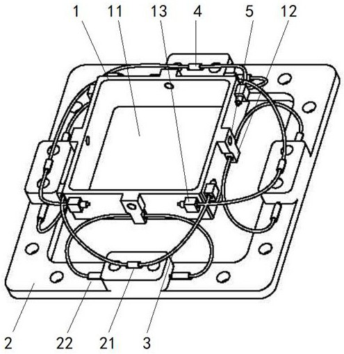
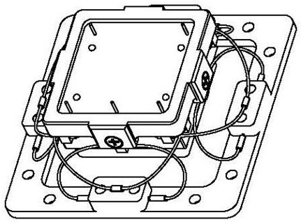
[0023] Such as figure 1 and figure 2 As shown, the present invention discloses a vibration damping device for an airborne crystal oscillator, including a vibration damping frame 1 and a mounting base 2, wherein: the vibration damping frame 1 is provided with a crystal vibration mounting part 11, and the vibration damping frame 1 and the mounting base 2 pass through Several groups of steel cables 3 are connected, and copper pipes 4 are crimped on the steel cables 3, and the vibration damping frame 1 and the mounting seat 2 are respectively connected through the copper pipes 4.

[0024] In the present invention, the copper pipe 4 is used for the connection between the single steel cable 3 and the damping frame 1 and the mounting base 2 . In a specific embodiment, copper tubes 4 with an outer diameter of 1 mm and an inner diameter of 0.7 mm are selected, and ...


PUM


Abstract

The invention discloses a vibration damper of airborne crystal oscillator. The vibration damper comprises a damping frame and an installation base, wherein a crystal oscillator installation part is arranged on the damping frame, the damping frame is connected with the installation base through a plurality of sets of steel cables, copper pipes are connected to the steel cables in a pressing mode, and the steel cables are connected with the damping frame and the installation base through the copper pipes respectively. When external vibration acts on the installation base, the external vibrationis transmitted to the vibration reduction frame after passing through the multiple sets of steel cables of the spatial three-dimensional structure, and the airborne crystal oscillator is rigidly installed on the vibration reduction frame. External strong vibration is transmitted to the crystal oscillator after being transmitted and attenuated by the vibration reduction device, energy transmitted to the crystal oscillator by the vibration is attenuated to different degrees along with the change of excitation frequency, the phase noise of the crystal oscillator is improved, and the anti-vibration performance of the crystal oscillator under the strong vibration condition is realized. The vibration damper has the advantages of being low in frequency, high in vibration isolation efficiency, small in magnification factor, wide in temperature range, light in weight and the like, can be used for rapid installation of airborne crystal oscillators of various specifications and models, and is lowin cost and easy and convenient to use and maintain.

Description

technical field [0001] The invention relates to the field of wireless communication, in particular to a vibration damping device for an airborne crystal oscillator. Background technique [0002] Crystal oscillator is an important part of radar, communication and other system equipment. It can achieve superior performance indicators under static conditions, but its performance indicators deteriorate sharply under vibration conditions, especially the phase noise indicators. Good adaptability to the mechanical environment is an important technical index of the crystal oscillator. The anti-vibration performance of the crystal oscillator directly affects the overall performance of the system. The vibration reduction measures of the crystal oscillator are an effective way to improve its anti-vibration performance. [0003] Due to the small size and light weight of the crystal oscillator itself, the vibration reduction of traditional airborne crystal oscillators is mainly achieved ...

Claims


Application Information

Patent Timeline
Patent Type & Authority Applications(China)
IPC IPC(8): H03H9/09
CPCH03H9/09
Inventor 叶锋穆晓华蒋创新戴梅生
Owner CHINA ELECTRONICS TECH GRP NO 26 RES INST
Why Eureka
Try Eureka