Cell battery cooled by cooling plates in radiator configuration

A single battery and cooling fin technology, applied to battery components, batteries, secondary batteries, etc., can solve the problems of occupying space, limiting the number of single batteries, and not describing the positioning of single battery cooling fins, etc., to increase The effect of capacity and heat energy

Pending Publication Date: 2021-02-05
PEZHO SITROEN AUTOMOBILS SA
View PDF1 Cites 0 Cited by
  • Summary
  • Abstract
  • Description
  • Claims
  • Application Information

AI Technical Summary

Problems solved by technology

The structure takes up space and severely limits the number of cells that can be loaded in a battery assembly due to assembly-related constraints that dictate gaps between modules
[0004] The second issue is in terms of cooling, where there is little contact between the cells and the cooling system, usually cooling fins, mainly due to the structure of the modules
[0008] However, this document does not describe how the cells are positioned relative to the cooling fins, in particular the number of cells given to each cooling fin

Method used


Image

  • Cell battery cooled by cooling plates in radiator configuration
  • Cell battery cooled by cooling plates in radiator configuration

Examples


Embodiment Construction

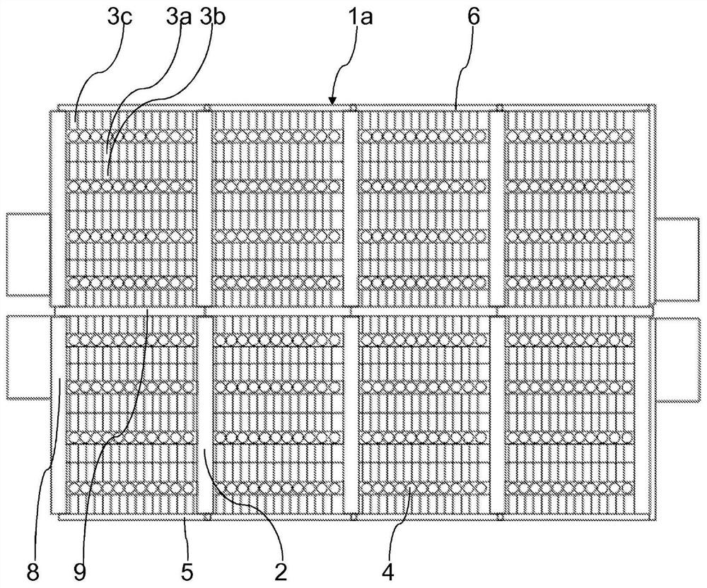
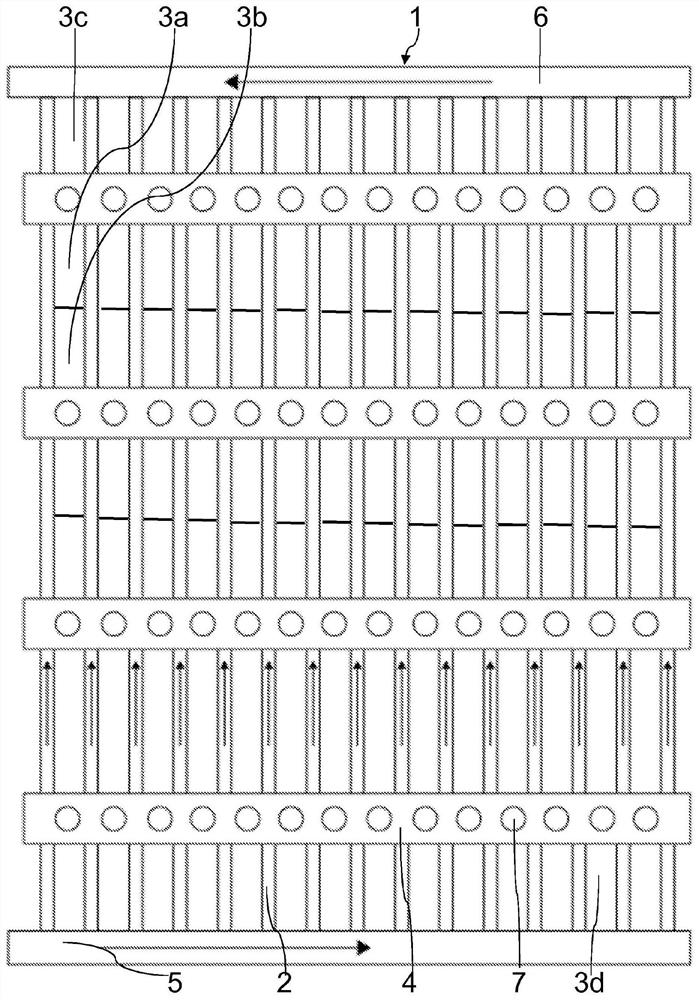
[0029] exist figure 1 with figure 2 In , only a single assembly bar 4, a single vent 7, a single cooling plate 2, and two cells 3a, 3b associated to all two associated cells are shown for simplicity, but for A description also refers to all equivalent elements.

[0030] refer to figure 2 , the present invention relates to a battery pack 1 comprising cooling fins 2, single cells 3a, 3b, 3c, 3d generating current, assembly rods 4, and inlet manifolds 5 and outlet manifolds 6 for cooling liquid, advantageously but not exclusively, The main component of the cooling liquid is the water circulating in the cooling fin 2, as shown by the arrow.

[0031] According to the invention, the cooling fins 2 are distributed in a plurality of parallel rows. Each row extends from the inlet manifold 5 to the outlet manifold 6 to ensure the circulation of the cooling liquid in the battery pack 1 .

[0032] Two single cells 3a, 3b storing and releasing electrochemical energy, advantageously ...


PUM


Abstract

The invention relates to a battery pack (1) comprising a cooling fin (2), current-generating battery cells (3a, 3b, 3c, 3d), an assembly rod (4) of battery cells (3a, 3b, 3c, 3d), and an inlet manifold (5) and an outlet manifold (6) of a cooling liquid circulating within the cooling fin (2). The cooling fins (2) are distributed in a plurality of parallel rows, each row extending from the inlet manifold (5) to the outlet manifold (6), two battery cells (3a, 3b) are associated with the cooling fins (2) between each pair of adjacent two assembly rods (4), and the two battery cells (3a, 3b) extendparallel to the associated cooling fins (2).

Description

technical field [0001] The present invention relates to a battery pack having unit batteries cooled by cooling fins, the battery pack employing a heat sink structure for arranging constituent elements of the battery pack facing each other. Background technique [0002] Today, there are three types of cells, which are prismatic cells, cylindrical cells and so-called propulsion cells. Assembly techniques have been similar for all three batteries. A small number of batteries are assembled together in modules, these modules are then assembled together with the cooling system, and finally all the modules are assembled in an assembly forming the battery pack. [0003] The first major problem with this approach is volume, since a bulky structure is placed around the small group of cells. This structure takes up space and severely limits the number of cells that can be loaded in a battery assembly because assembly-related constraints dictate gaps between modules. [0004] The sec...

Claims


Application Information

Patent Timeline
IPC IPC(8): H01M10/6557H01M10/6555H01G11/12H01M10/6567H01M50/204
CPCH01G11/12H01M10/625H01M10/6555H01M10/6557H01M10/6567H01G11/18Y02E60/10H01M50/209H01M50/249H01M10/647H01M2220/20H01M50/264H01M10/613H01M50/30H01M50/204
Inventor 弗雷德里克·杜富尔本杰明·珀蒂艾瑞克·杜兰德
Owner PEZHO SITROEN AUTOMOBILS SA
Why Eureka
Try Eureka