Aortic root stent system

A stent system and aortic technology, which is applied in the direction of stents, blood vessels, and devices of human tubular structures, can solve the problems of small anchoring area, weak positioning, and easy displacement, so as to improve stability and increase the scope of application , the effect of not easy to shift

Pending Publication Date: 2021-02-09
陈宏伟
View PDF1 Cites 3 Cited by
  • Summary
  • Abstract
  • Description
  • Claims
  • Application Information

AI Technical Summary

Problems solved by technology

[0004] The present invention provides an aortic root stent system to solve the disadvantages of the existing aortic valve annulus, which only relies on anchoring feet for positioning, the anchoring area is small, the positioning is not firm, and it is easy to shift.

Method used


Image

  • Aortic root stent system
  • Aortic root stent system
  • Aortic root stent system

Examples


Embodiment 1

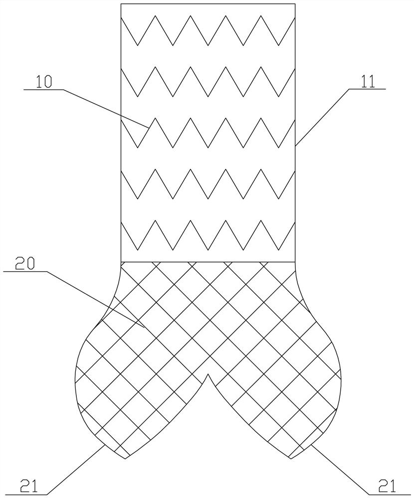
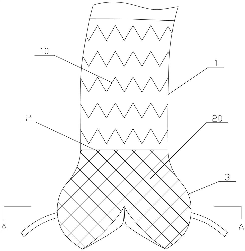
[0031] A kind of aortic root stent system, with reference to figure 1 and figure 2 , including an aortic stent 10 and a sinus anchor stent 20 . The aortic stent 10 is provided with a covering film 11, and the aortic stent 10 is correspondingly attached to the inner wall of the ascending aorta 1, and extends from the inner wall of the distal end of the ascending aorta 1 to the inner wall of the sinotubular junction 2. When a dissection occurs in a certain part of the ascending aorta 1, the corresponding part of the aortic stent 10 is provided with a film-11, and the surrounding part is also provided with a film-11 as an anchoring area, and the aortic stent 10 The other parts of the film can be provided with a film-11, and also can not be provided with a film-11.

[0032] refer to Figure 1 to Figure 3 The bottom of the proximal end of the aortic stent 10 is also fixed with a sinus anchoring stent 20 . The sinus anchoring stent 20 abuts against the inner wall of the aortic s...

Embodiment 2

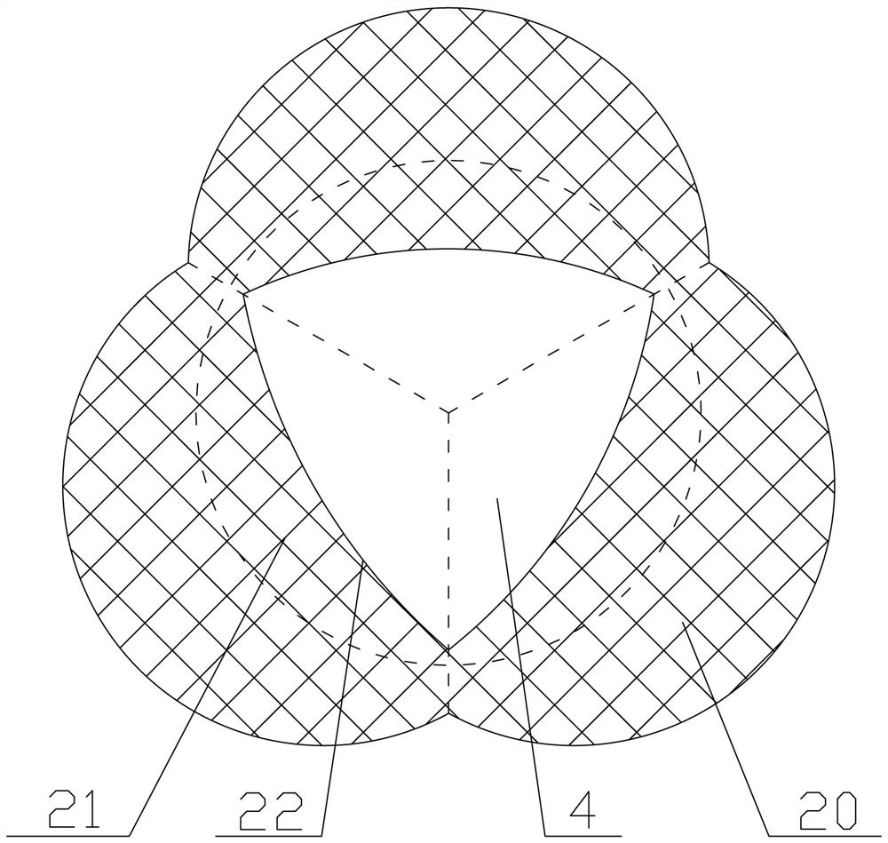
[0037] refer to Figure 4 and Figure 5 , the aortic root stent system of this embodiment also includes an aortic stent 10 and a sinus anchoring stent 20 . The aortic stent 10 is correspondingly attached to the inner wall of the ascending aorta 1 , and extends from the inner wall of the distal end of the ascending aorta 1 to the inner wall of the sinotubular junction 2 , and the aortic stent 10 is provided with a covering film 1 . The sinus anchoring stent 20 is correspondingly attached to the inner wall of the aortic sinus 3, and extends downward from the sinotubular junction 2, and the bottom of the sinus anchoring stent 20 forms several coronary valves that are correspondingly attached to the aortic sinus Stents 21, the outer peripheral surfaces of several coronal valve stents 21 form a garlic clove-like structure.

[0038] The main difference between this embodiment and the first embodiment is that: the aortic stent 10 is a covered stent with a first covering 11 , while ...

Embodiment 3

[0040] refer to Figure 6The aortic root stent system of this embodiment also includes an aortic stent 10 and a sinus anchoring stent 20. The bottom of the sinus anchoring stent 20 forms a plurality of corresponding coronary valve stents 21 attached to the aortic sinus. The main difference between the present embodiment and the second embodiment is that: when the dissection of the sinus lesion in the present embodiment occurs below the coronary artery ostium, therefore, the sinus anchoring stent 20 corresponding to the coronary artery ostium must be provided with an overlay Membrane 2 23, through-hole 24 corresponding to the opening of the coronary artery must be opened on the covering membrane 2 23, so as to ensure the normal supply of coronary artery blood flow.


PUM


Abstract

The invention provides an aortic root stent system. The aortic root stent system comprises an aortic stent and a sinus anchoring stent, wherein the aortic stent is correspondingly arranged on the inner wall of the ascending aorta; the sinus anchoring stent is attached to the inner wall of the aortic sinus and extends downwards from the junction of sinus canals; the bottom of the sinus anchoring stent extends inwards to form a plurality of crown valve stents attached to the aortic sinus; the peripheral surfaces of the crown valve stents form a garlic-clove-shaped structure; the top ends of theinner sides of the crown valve stents correspondingly extend to the outer side of the valve ring; and an opening allowing valve leaflets to move freely is formed in the tail end of each crown valve stent. For the aortic root stent system, the crown valve stents can increase the anchoring area of the whole sinus anchoring stent in the aortic valve, the positioning is firm, displacement seldom occurs under the impact of blood flow, and thus the stability of the aortic root anchoring system in the aortic valve is improved.

Description

technical field [0001] The invention relates to the field of implantable blood vessels, and more specifically refers to an aortic root stent system. Background technique [0002] The Chinese invention patent with the application publication number of CN 105287051A discloses an artificial aortic valve ring system implanted via peripheral arterial approach, including a valve ring support at the distal end and an anchoring foot at the proximal end. The anchoring foot is fixedly connected, and the annulus support is tubular and has a grid structure; the anchoring foot is arranged along the periphery of the annulus support, and is used to be embedded in the chamber structure of the root of the ascending aorta to fix the annulus. The artificial aortic valve ring system, the artificial aortic valve ring system can be transformed between a radially expanded first configuration and a radially contracted second configuration; The second part of the heart end, the anchoring foot is fi...

Claims


Application Information

Patent Timeline
Patent Type & Authority Applications(China)
IPC IPC(8): A61F2/07A61F2/90
CPCA61F2/07A61F2/90
Inventor 陈宏伟陈欣榆
Owner 陈宏伟
Why Eureka
Try Eureka