Novel multifunctional new energy automobile charging pile

A new energy vehicle, multi-functional technology, applied in electric vehicle charging technology, charging stations, electric vehicles, etc., can solve problems such as winding, affecting the normal use of output lines, and easy slipping of output lines

Inactive Publication Date: 2021-02-09
高洁
View PDF0 Cites 1 Cited by
  • Summary
  • Abstract
  • Description
  • Claims
  • Application Information

AI Technical Summary

Problems solved by technology

[0004] The purpose of the present invention is to provide a new multi-functional new energy vehicle charging pile to solve the problem that the output line of the existing new energy vehic...

Method used


Image

  • Novel multifunctional new energy automobile charging pile
  • Novel multifunctional new energy automobile charging pile
  • Novel multifunctional new energy automobile charging pile

Examples


Embodiment 1

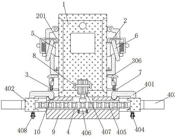
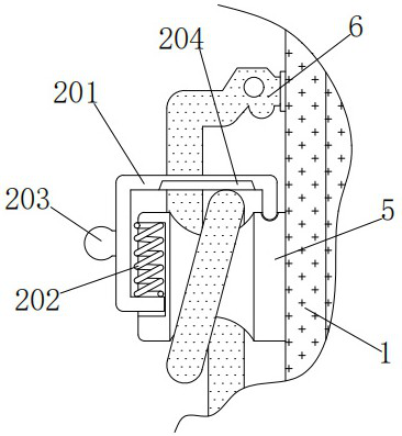
[0034] A new type of multi-functional new energy vehicle charging pile, including a charging column 1, a sheave 5 is fixedly connected to the top of the left and right sides of the charging column 1, and a take-up mechanism 2 is installed on the outside of the two sheaves 5, and the take-up mechanism 2. It includes a curved plate 201, a compression spring 202, a ball 203 and a rubber pad 204. The bottom of the curved plate 201 fits the bottom of the left notch of the sheave 5. The force of the curved plate 201 can pass through the left groove of the sheave 5. The inside of the mouth slides up and down, the inner bottom of the curved plate 201 is fixedly connected with the bottom of the compression spring 202, the top of the compression spring 202 is fixedly connected with the top of the left notch of the sheave 5, and the left side of the curved plate 401 is connected with the ball 203 The ball 203 is convenient to pull the curved plate 401 to move, and the inner top of the cur...

Embodiment 2

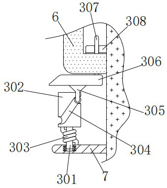
[0036] As an option, see figure 1 , 3 And 4, a new multi-functional new energy vehicle charging pile, the left and right sides of the charging pole 1 are fixed with straight plates 7, and the tops of the two straight plates 7 are equipped with a pressing mechanism 3, which includes short rods 301, Cylinder 302, torsion spring 303, curved groove 304, protruding rod 305, curved block 306, vertical rod 307 and sleeve plate 308, the bottom of short rod 301 is connected with the top left side of straight board 7 in rotation, and short rod 301 is stressed through the straight board 7 The bearing on the left side of the top rotates, the top of the short rod 301 is fixedly connected to the bottom of the cylinder 302, the outer wall of the short rod 301 is socketed with the inner wall of the torsion spring 303, and the upper and lower sides of the torsion spring 303 are connected to the cylinder 302 respectively. The bottom of the cylinder 302 is fixedly connected to the top of the st...

Embodiment 3

[0039] As an option, see figure 1, 5 And 6, the new multifunctional new energy vehicle charging pile, the left and right sides of the inner wall of the arc groove 10 are equipped with an adjustment mechanism 4, the adjustment mechanism 4 includes a curved rod 401, a slot plate 402, an arc plate 403, a bump 404, and a gear 405 , a thick rod 406, a motor 407 and a roller 408, the inner sides of the bottom of the two curved rods 401 are respectively slidingly engaged with the left and right sides of the inner wall of the circular groove 10, and the curved rod 401 is forced to make a circular motion through the inner wall of the circular groove 10, The bottoms of the two curved rods 401 are fixedly connected to the left and right sides of the top of the groove plate 402 respectively, and the left and right sides of the groove plate 402 are fixedly connected to the inner side of the arc plate 403 respectively, and the inner wall of the groove plate 402 is equidistantly processed wi...


PUM


Abstract

The invention discloses a novel multifunctional new energy automobile charging pile which comprises a charging column, grooved pulleys are fixedly connected to the upper portions of the left side andthe right side of the charging column correspondingly, take-up mechanisms are installed on the outer sides of the two grooved pulleys correspondingly, and each take-up mechanism comprises a bent plate, a compression spring, a ball and a rubber pad, wherein the bottom of the bent plate is attached to the bottom of a left notch of the grooved pulley, and the bottom of the inner side of the bent plate is fixedly connected with the bottom of a compression spring. An output line is prevented from slipping off, winding is avoided, normal use of the output line is guaranteed, falling force is buffered, connection abrasion is avoided, the output line is prevented from being broken, maintenance cost is saved, the practicability is improved, an adjusting mechanism gear is matched with a protruding block to drive a groove plate to rotate, position adjustment is achieved, changing can be carried out according to terrains, and the working difficulty is reduced; the working efficiency is improved; through the adjusting mechanism, the groove plate can be finely adjusted in the using process, so that the arc plate is matched with the rear wheel, it is guaranteed that the vehicle body is stably parked, and using and popularization are convenient.

Description

technical field [0001] The invention relates to the technical field of a novel multifunctional new energy vehicle charging pile, in particular to a novel multifunctional new energy vehicle charging pile. Background technique [0002] The function of the new energy vehicle charging pile is similar to that of the fuel dispenser in the gas station. It can be fixed on the ground or wall, and installed in the parking lot or charging station of public buildings and residential areas. It can charge various types of electric vehicles according to different voltage levels. . [0003] There is no limit to the direct winding between the output wire and the sheave when the existing new energy vehicle charging pile is in use. Use, increase maintenance costs, reduce usability, and the installation of the charging column cannot be adjusted, and it is easy to conflict with the terrain, which increases the difficulty of work and reduces efficiency. , troublesome to use, does not meet the n...

Claims


Application Information

Patent Timeline
IPC IPC(8): B60L53/31B60L53/18
CPCB60L53/18B60L53/31Y02T10/70Y02T10/7072Y02T90/12Y02T90/14
Inventor 不公告发明人
Owner 高洁
Why Eureka
Try Eureka