An anti-clogging conveying pipe structure and anti-clogging method for pneumatic conveying of viscous materials

A pneumatic conveying and conveying pipe technology, applied in the field of anti-blocking conveying pipe structure, can solve problems such as pipe blockage, straight pipe blockage, and bend pipe wear, so as to reduce impact force and corrosion, solve wear and blockage, and avoid wear effect

Active Publication Date: 2022-04-29
常州逸盛机电技术有限公司
View PDF13 Cites 0 Cited by
  • Summary
  • Abstract
  • Description
  • Claims
  • Application Information

AI Technical Summary

Problems solved by technology

In the process of pneumatic conveying, there will be some factors that affect the continuous conveying of materials, such as the blockage of the pipeline and the damage of the elbow. The blockage of the pipeline will seriously affect the conveying of the material, and it will cause an explosion in severe cases.
[0003] However, viscous materials are constantly rubbing against the inner wall of the pipeline during the transportation process, generating electrostatic force, attracting each other under the action of electrostatic force, and coagulating into agglomerates, which will occur in the straight pipe section or the curved pipe section of the conveying pipe structure. On the one hand, the material itself is adhesive, and the effect of electrostatic force is more obvious during the conveying process of viscous materials. The clogging phenomenon of viscous materials under the action of electrostatic force and centrifugal force is more serious at the elbow; secondly, the straightness of the conveying pipe The wear of the inner wall of the pipe section is mainly the friction and wear caused by the friction between the material and the inner wall, while the wear of the elbow section is mainly the impact wear of the material on the inner wall of the bend during the direction change process, so the straight pipe in the pneumatic conveying system for viscous materials is easy A blockage occurs with severe wear and blockage at the elbow
[0004] At present, in order to solve the above technical problems, an air blowing bypass pipe is added to the conveying pipeline to improve the clogging situation. As long as the conveying pipe structure works normally, this kind of blowing bypass pipe will always be in a state of ventilation, and the air consumption is relatively large, while the blowing The setting of the air bypass pipe is only for the blockage of the straight pipe, and cannot effectively solve the blockage and wear of the elbow; patent number 201920903255.7 is an anti-blocking device for a pneumatic conveying system, which uses a combination of air jet anti-blocking and vibration anti-blocking The anti-clogging treatment of the pneumatic conveying pipe is carried out in the same way, but there are the following defects: 1. The conveying pipe is shaken by knocking on the outside of the conveying pipe, so that the blocked material in the conveying pipe can be evacuated, but this structure is only applicable to the straight pipe part and cannot Effectively solve the blockage of viscous materials at the elbow, and the blockage of viscous materials at the elbow is often the most serious; 2. Knocking on the outer tube of the conveying pipe can easily cause local deformation of the conveying pipe or affect the flow of the conveying pipe Structural strength, which greatly shortens the service life of the delivery pipe

Method used


Image

  • An anti-clogging conveying pipe structure and anti-clogging method for pneumatic conveying of viscous materials
  • An anti-clogging conveying pipe structure and anti-clogging method for pneumatic conveying of viscous materials
  • An anti-clogging conveying pipe structure and anti-clogging method for pneumatic conveying of viscous materials

Examples


Embodiment approach

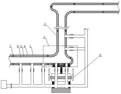
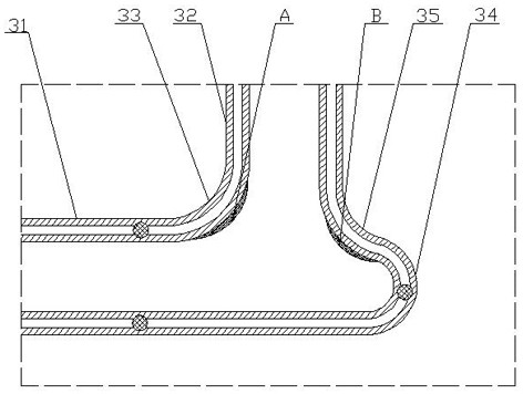
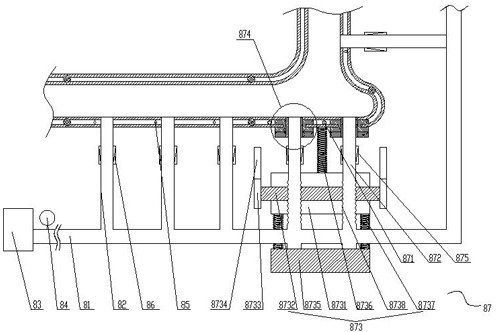
[0041] Such as figure 1 , figure 2 It shows an embodiment of an anti-clogging conveying pipe structure for viscous material pneumatic conveying according to the present invention, which includes horizontal pipes 1 and longitudinal pipes 2 arranged at intervals in sequence, and there is an elbow between the horizontal pipe 1 and the longitudinal pipe 2 3. The horizontal pipe 1, the longitudinal pipe 2, and the curved pipe 3 are integrated to form a conveying pipe. The horizontal pipe 1, the longitudinal pipe 2, and the curved pipe 3 all include an aluminum alloy outer pipe body 4 and a rubber inner pipe body 5. The aluminum alloy outer pipe body There is a gap 6 between the pipe body 4 and the rubber inner pipe body 5, and the connection between the aluminum alloy outer pipe body 4 and the rubber inner pipe body 5 is realized by a plurality of sealing rings 7 distributed at equal intervals. A controllable vibration blowing mechanism 8 set in the extension direction;

[0042]...


PUM


Abstract

The invention relates to an anti-clogging conveying pipe structure and an anti-clogging method for viscous material pneumatic conveying, comprising horizontal pipes and longitudinal pipes arranged at intervals in sequence, there is an elbow between the horizontal pipes and the longitudinal pipes, the horizontal pipes, the longitudinal pipes The delivery pipe is formed integrally with the bent pipe, the horizontal pipe, the longitudinal pipe and the bent pipe all include an aluminum alloy outer pipe body and a rubber inner pipe body, there is a gap between the aluminum alloy outer pipe body and the rubber inner pipe body, and the aluminum alloy The connection between the outer tube body and the rubber inner tube body is realized through a plurality of sealing rings distributed at equal intervals, and also includes a controllable vibration blowing mechanism arranged along the extending direction of the delivery tube. The invention has the following advantages: effectively solving the wear and blockage of the inner wall of the straight pipe part and the bent pipe part, and ensuring the structural strength of the conveying pipe.

Description

Technical field: [0001] The invention belongs to the field of pneumatic conveying, and in particular relates to an anti-clogging conveying pipe structure and an anti-clogging method for viscous material pneumatic conveying. Background technique: [0002] Pneumatic conveying system, also known as air conveying, is a specific application of fluidization technology that uses the energy of airflow to convey granular or powdery materials along the direction of airflow in a sealed pipeline. In the process of pneumatic conveying, there will be some factors that affect the continuous conveying of materials, such as the blockage of the pipeline and the damage of the elbow. The blockage of the pipeline will seriously affect the conveying of the material, and it will cause an explosion in severe cases. [0003] However, viscous materials are constantly rubbing against the inner wall of the pipeline during the transportation process, generating electrostatic force, attracting each other...

Claims


Application Information

Patent Timeline
Patent Type & Authority Patents(China)
IPC IPC(8): B65G53/52
CPCB65G53/521
Inventor 于雷
Owner 常州逸盛机电技术有限公司
Why Eureka
Try Eureka