

Silicon rod splicing device capable of splicing cylindrical silicon rods
A technology of splicing device and silicon rod, which is applied in crystal growth, post-processing details, post-processing and other directions, can solve the problems of waste of production capacity, reduction of crystal rod output rate, and no automatic mechanical device.
- Summary
- Abstract
- Description
- Claims
- Application Information
AI Technical Summary
Problems solved by technology
Method used
Image

Examples
Embodiment 1
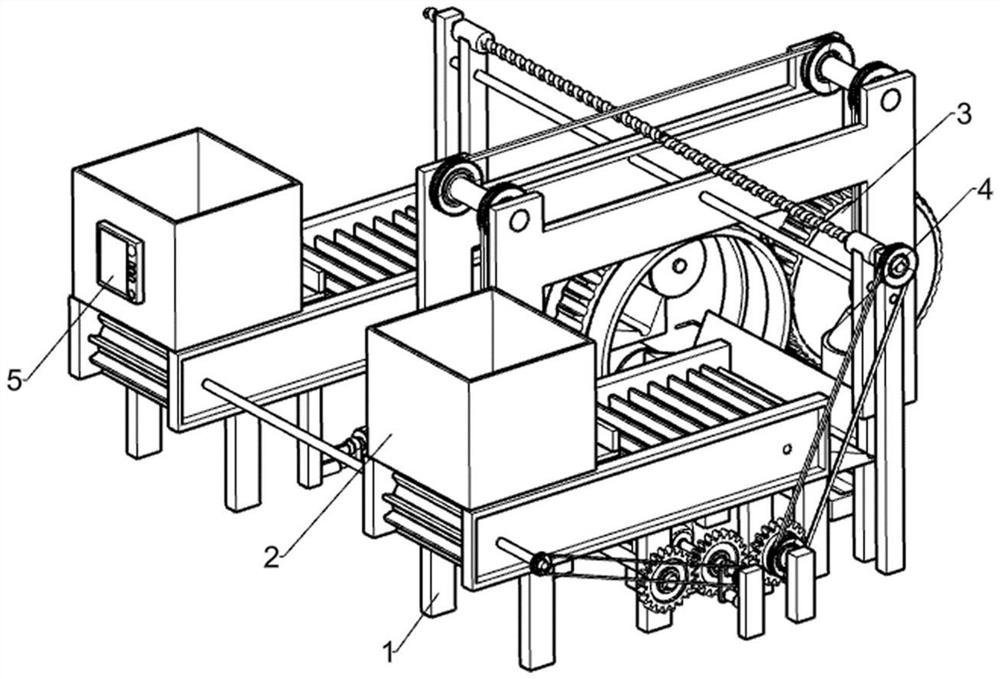
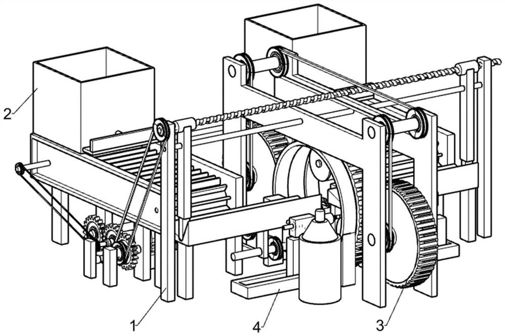
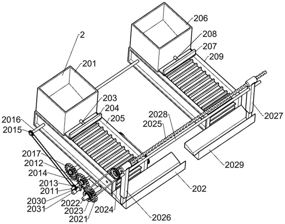
[0027] A silicon rod splicing device capable of splicing cylindrical silicon rods, such as Figure 1-7 As shown, it includes an underframe 1, a feeding unit 2, a winding unit 3, an injection unit 4 and a control panel 5; the underframe 1 is connected with the feeding unit 2; the underframe 1 is connected with the winding unit 3; the underframe 1 is connected with the injection unit 4; the chassis 1 is connected with the control panel 5; the feeding unit 2 is connected with the winding unit 3.
[0028] Working principle: When in use, first place the silicon rod splicing device that can splice cylindrical silicon rods to the position to be used, then connect the external power supply, and start it through the control panel 5; first put the short silicon rods on the loading unit 2, Use the feeding unit 2 to position the two short silicon rods in contact with each other, then use the winding unit 3 to wrap the splicing seam tightly with adhesive tape, then inject the fixative into...
PUM
 Abstract
Description
Claims
Application Information