Sample detection system

A sample detection and sample rack technology, applied in the direction of measuring devices, biological testing, material inspection products, etc., can solve the problems of high layout cost, difficulty in realization, and complex control functions of the master control equipment, and achieve low layout cost and simple control functions Effect

Pending Publication Date: 2021-02-09
SHENZHEN MINDRAY BIO MEDICAL ELECTRONICS CO LTD
View PDF6 Cites 0 Cited by
  • Summary
  • Abstract
  • Description
  • Claims
  • Application Information

AI Technical Summary

Problems solved by technology

[0005] In the aforementioned assembly line joint detection system, the control function of the master control equipment is relatively complicated, and the layout cost is relatively high. In addition, when the sample analyzer in the pipeline joint detection system needs to be changed, such as adding a new sample analyzer, it is necessary to adjust the total control equipment. It is time-consuming and labor-intensive to change the control logic of the equipment, and it is difficult to implement

Method used


Image

  • Sample detection system
  • Sample detection system
  • Sample detection system

Examples


Embodiment 1

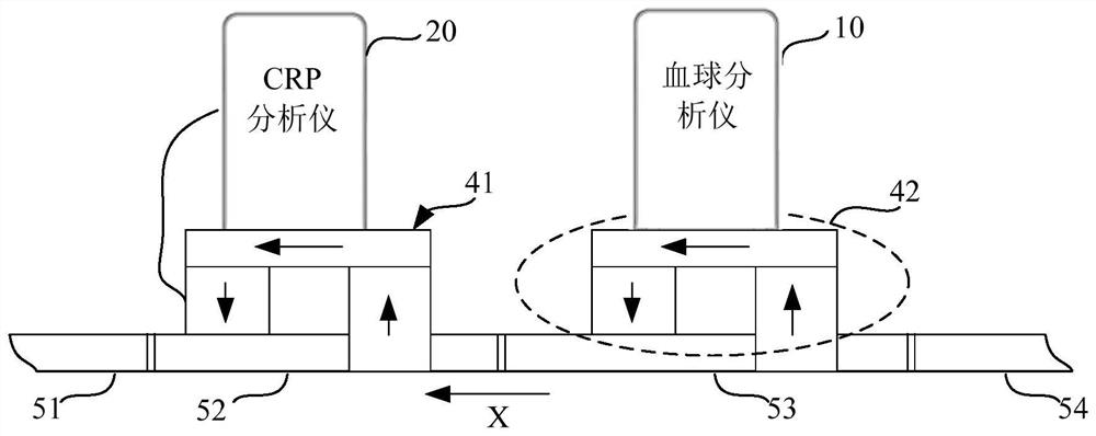
[0062] figure 1 It is a schematic structural diagram of a sample detection system provided in an embodiment of the present application. like figure 1 As shown, the sample detection system includes: a first CRP analyzer 20, at least one second sample analyzer and a transmission device.

[0063] Here, both the first CRP analyzer 20 and the at least one second sample analyzer can themselves have internal controllers.

[0064] exist figure 1 Herein, the second sample analyzer takes the hematology analyzer 10 as an example. In the embodiment of the present application, the second sample analyzer may also include one or more combinations of a hematology analyzer, a slide stainer and a saccharification instrument.

[0065] The function of the transfer device is to transfer the sample rack loaded with blood sample containers. Through the transfer of the transfer device, the sample containers can be transferred to the first CRP analyzer 20 or any sample analyzer for testing.

[006...

Embodiment 2

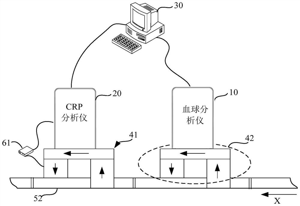
[0085] image 3 It is a schematic diagram of the second embodiment provided for the sample detection system of the present application.

[0086] like image 3 As shown, the difference between the second embodiment and the first embodiment is that the sample detection system further includes: a main control device 30 .

[0087] In the embodiment of the present application, the first CRP analyzer 20 and each second sample analyzer (hematology analyzer 10 shown in the figure), for example, their internal controllers are all connected to the main control device 30, that is, they are electrically connected or The purpose of adding the communication connection to the main control device 30 is to collect the test result data and instrument status data of the first CRP analyzer 20 and each second sample analyzer and perform centralized management and display.

[0088] In a specific application, for the CRP analyzer and all sample analyzers for joint detection on the assembly line, t...

Embodiment 3

[0094] like Figure 5 As shown, it is the third embodiment provided by this application, and the sample detection system provided in this embodiment may further include: a transmission control device 90 .

[0095] The transmission control device 90 is electrically connected to each transmission mechanism, and the function of the transmission control device 90 is to schedule the sample rack to be transferred in the transmission channel, and can transfer the sample rack to the position corresponding to any feeding mechanism in the transmission channel, so that Then send the sample rack into the CRP analyzer or the second sample analyzer for testing. In the embodiment of the present application, the transmission control device 90 may use electronic devices with computing capabilities such as single-chip microcomputers or programmable logic controllers. In addition, the communication between the transmission control device 90 and each transmission mechanism can be carried out thr...


PUM


Abstract

The invention relates to a sample detection system which comprises a first CRP analyzer, at least one second sample analyzer and transmission equipment. The transmission equipment comprises at least two feeding mechanisms with detection channels and a plurality of sections of transmission mechanisms which are sequentially connected, and a transmission channel is formed among the plurality of sections of transmission mechanisms; at least two feeding mechanisms are arranged in the transmission direction of the transmission channel at intervals. The first CRP analyzer and each sample analyzer respectively correspond to one feeding mechanism; and the first CRP analyzers are electrically connected with the corresponding feeding mechanisms. Therefore, the sample detection system can be quickly expanded when detecting CRP items as required and is , convenient and simple.

Description

technical field [0001] The present application relates to the field of medical diagnostic equipment, in particular to a sample detection system. Background technique [0002] CRP (C-reactive protein, C-reactive protein) is an acute phase response protein, which normally exists in small amounts in human body fluids, but increases to varying degrees in infectious diseases, and has important clinical application value. Especially in recent years, with the rapid development of bedside rapid detection technology, the application of CRP in clinical infectious diseases has become more extensive, and it has once again become the focus of clinical research. [0003] Blood routine is one of the three major routine examinations, and it is also one of the commonly used auxiliary examination methods for doctors to diagnose diseases. Doctors can assist in judging physical conditions by observing changes in the number and morphology of blood cells. There is a high correlation between CRP ...

Claims


Application Information

Patent Timeline
Patent Type & Authority Applications(China)
IPC IPC(8): G01N35/10G01N33/68
CPCG01N35/1081G01N33/6803
Inventor 张军伟郁琦
Owner SHENZHEN MINDRAY BIO MEDICAL ELECTRONICS CO LTD
Why Eureka
Try Eureka