

Two-dimensional moving magnet type rapid reflector device
A mirror and moving magnet technology, applied in optical components, optics, instruments, etc., can solve problems such as thermal deformation of mirrors, achieve the effects of reducing radial gap, reasonable structure setting, and avoiding cable dragging
- Summary
- Abstract
- Description
- Claims
- Application Information
AI Technical Summary
Problems solved by technology
Method used
Image

Examples
Embodiment Construction
[0068] In order to make the purpose, technical solutions and advantages of the embodiments of the present invention clearer, the technical solutions in the embodiments of the present invention will be clearly and completely described below in conjunction with the drawings in the embodiments of the present invention. Obviously, the described embodiments It is a part of embodiments of the present invention, but not all embodiments. The components of the embodiments of the invention generally described and illustrated in the figures herein can be arranged and designed in a variety of different configurations.
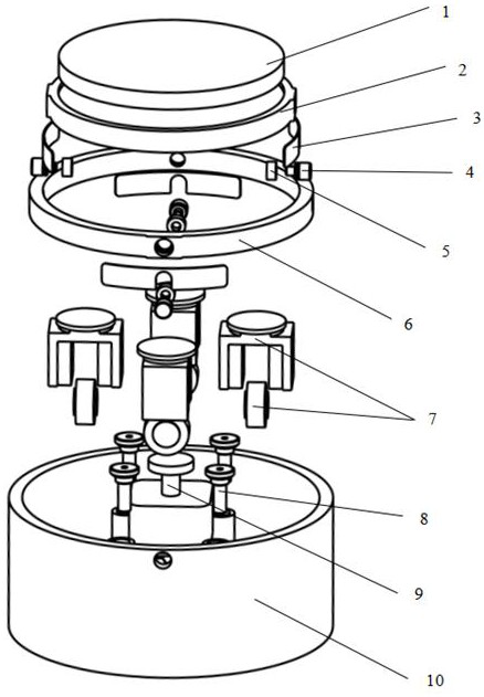
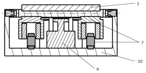
[0069] Please refer to Figure 1 to Figure 3 , the first embodiment of the present invention provides a two-dimensional moving magnet fast mirror device, including: a mirror 1, a rigid support assembly, a mirror bracket 2, a voice coil motor 7, a displacement measuring sensor 8 and a housing 10 .
[0070] The reflector 1 is supported on the front end of the base of the h...
PUM
 Abstract
Description
Claims
Application Information