Method for automatically identifying and calculating antenna pattern pits

An antenna pattern and automatic identification technology, which is applied in the field of antenna manufacturing, can solve the problems of lack of effective identification of antenna pattern pits, large subjective influence, and low efficiency of manual identification, so as to shorten the pit processing cycle and improve efficiency and quality , High data processing efficiency

Active Publication Date: 2021-02-09
SOUTHWEST CHINA RES INST OF ELECTRONICS EQUIP
View PDF9 Cites 1 Cited by
  • Summary
  • Abstract
  • Description
  • Claims
  • Application Information

AI Technical Summary

Problems solved by technology

[0003] Aiming at the above-mentioned deficiencies in the prior art, a method for automatically identifying and calculating antenna pattern pits provided by the present inventi...

Method used


Image

  • Method for automatically identifying and calculating antenna pattern pits
  • Method for automatically identifying and calculating antenna pattern pits
  • Method for automatically identifying and calculating antenna pattern pits

Examples


Embodiment Construction

[0025] The specific embodiments of the present invention are described below so that those skilled in the art can understand the present invention, but it should be clear that the present invention is not limited to the scope of the specific embodiments. For those of ordinary skill in the art, as long as various changes Within the spirit and scope of the present invention defined and determined by the appended claims, these changes are obvious, and all inventions and creations using the concept of the present invention are included in the protection list.

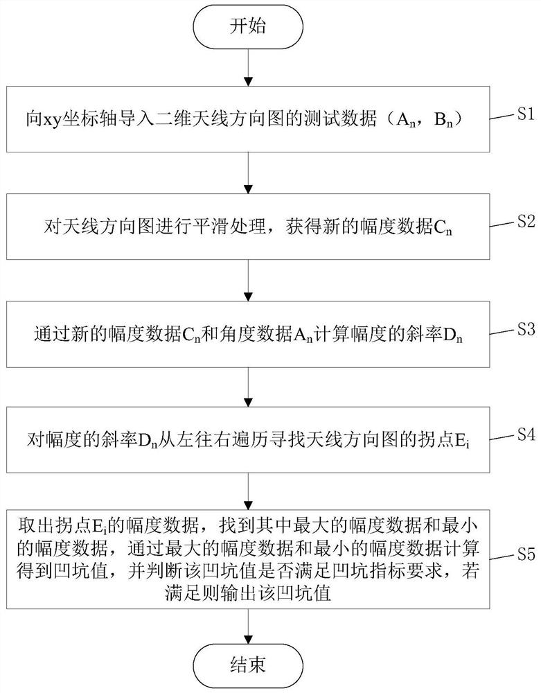
[0026] Such as figure 1 As shown, a method for automatically identifying and calculating antenna pattern pits includes the following steps:

[0027] S1, import the test data of the two-dimensional antenna pattern to the xy coordinate axis (A n , B n )(n=1,2,3...m), A n is the angle data in the test data, B n is the amplitude data corresponding to the angle data, and m is the number of test data;

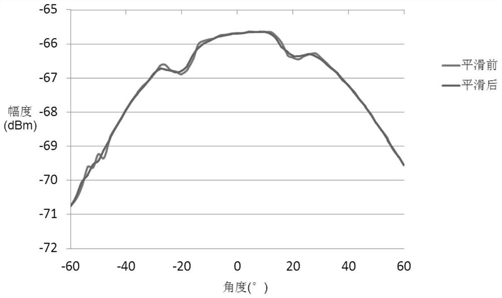
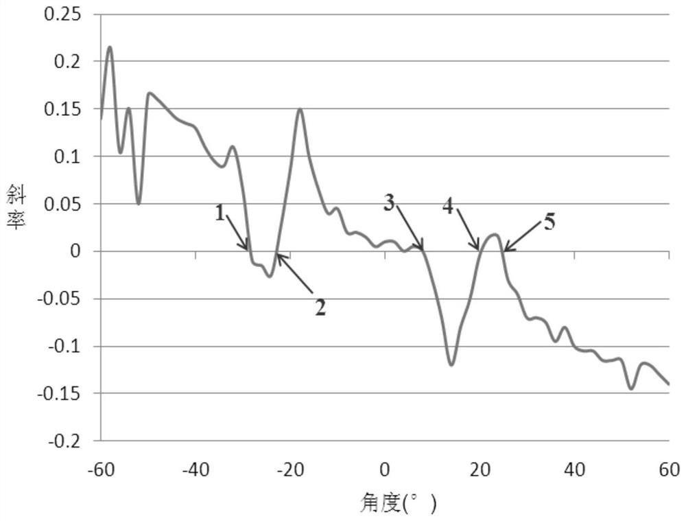
[0028] S2. Smoothing ...


PUM


Abstract

The invention discloses a method for automatically identifying and calculating antenna pattern pits. The invention provides a special algorithm, and the algorithm can eliminate the interference, caused by a test environment error, of directional diagram small sawteeth on pit recognition, and carries out the precise recognition and calculation of pits. Meanwhile, the calculation process is simple and clear, data processing efficiency is high, and software implementation is facilitated. At present, when engineering application is achieved, the pit processing period in the antenna manufacturing process is shortened by 96%, and the pit recognition efficiency and quality are remarkably improved.

Description

technical field [0001] The invention relates to the technical field of antenna manufacturing, in particular to a method for automatically identifying and calculating pits in an antenna pattern. Background technique [0002] The antenna pattern is an important basis for measuring the performance of the antenna, from which various parameters of the antenna can be calculated and extracted. At present, the antenna pattern data processing business is widely used in the manufacturing activities of various antennas. At present, the pits in the antenna pattern are mainly identified by the naked eye, which is inefficient and easily affected by subjectivity. The existing methods related to pit identification cannot eliminate the interference of the small sawtooth in the antenna pattern caused by the error of the test environment on the pit identification. Therefore, the pit identification method cannot meet the pit identification and calculation requirements of the antenna pattern. ...

Claims


Application Information

Patent Timeline
IPC IPC(8): G06T7/00G06T5/00
CPCG06T7/0004G06T5/002
Inventor 李仪张凌聂剑坤张锋王兆麒汪子琦刘明
Owner SOUTHWEST CHINA RES INST OF ELECTRONICS EQUIP
Why Eureka
Try Eureka