Power battery clamp baking device

A power battery and baking device technology, which is applied in the manufacture of secondary batteries, battery pack components, circuits, etc., can solve the problems of power battery hazards, battery heating, and insufficient baking, so as to prevent uneven heating and improve The effect of applicability

Active Publication Date: 2021-02-09
GUANGDONG POLYTECHNIC NORMAL UNIV
View PDF6 Cites 0 Cited by
  • Summary
  • Abstract
  • Description
  • Claims
  • Application Information

AI Technical Summary

Problems solved by technology

[0003] The electrolyte of the power battery is an organic substance without water molecules. The existence of water is extremely harmful to the power battery and will cause the battery to heat up and explode. Therefore, it needs to be baked before the battery is injected and sealed to remove the presence of water. Control the water content to improve the service life of the battery, but the existing baking device has insufficient or uneven baking, which reduces the service life and quality of the battery. Therefore, in view of the above current situation, it is urgent to develop a power Baking device for battery fixtures to overcome deficiencies in current practical applications

Method used


Image

  • Power battery clamp baking device
  • Power battery clamp baking device
  • Power battery clamp baking device

Examples


Embodiment 1

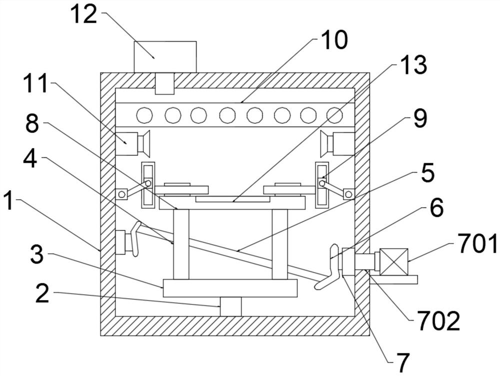
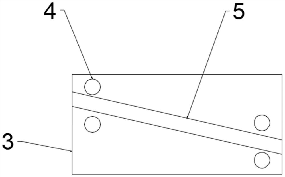
[0022] see Figure 1-3 , in an embodiment of the present invention, a power battery fixture baking device includes a box body 1, a rotating rod 2 is movably connected in the middle of the bottom of the inner wall of the box body 1, and a bottom plate 3 is fixedly connected to the top of the rotating rod 2. The upper surface of the base plate 3 is fixedly connected with connecting rods 4, and the connecting rods 4 are provided with four and there are two respectively at the left and right ends of the upper surface of the base plate 3, and the connecting rods 4 are staggeredly installed on the upper end of the base plate 3. One side of the inner wall of the box body 1 is fixedly connected with a mounting block, one end of the mounting block is fixedly connected with an insertion rod 5, and the insertion rod 5 passes through the gap between two connecting rods 4 and the other end is fixedly connected with a connection block 6, The other end of the connecting block 6 is provided w...

Embodiment 2

[0026] see Figure 1-3 , in this embodiment, the drive mechanism 7 includes a first motor 701, a mounting frame is fixedly connected to one side of the outer wall of the box body 1, a first motor 701 is provided on the upper surface of the mounting frame, and the first motor 701 The output shaft of the output shaft is fixedly connected with a rotating shaft 702 through a coupling, and the rotating shaft 702 passes through the side wall of the box body 1 and is fixedly connected with the connecting block 6, and the first motor 701 is started, and the first motor 701 drives the rotating shaft 702 to rotate, so that The rotating shaft 702 drives the connecting block 6 to rotate, realizing that the insertion rod 5 can drive the base plate 3 and the connecting plate 8 to rotate left and right under the restriction of the connecting rod 4, thereby driving the rotation angle of the power battery, so that the power battery is heated under the fixation of the clamping assembly Uniformi...


PUM


Abstract

The invention relates to the technical field of battery clamp baking devices, in particular to a power battery clamp baking device which comprises a box body. A rotating rod is movably connected to the middle of the bottom of the inner wall of the box body, a bottom plate is fixedly connected to the top end of the rotating rod, and connecting rods are fixedly connected to the upper surface of thebottom plate. Four connecting rods are arranged, the left and right ends of the upper surface of the bottom plate are each equipped with two connecting rods, and the connecting rods are mounted at theupper end of the bottom plate in a staggered manner. A mounting block is fixedly connected to one side of the inner wall of the box body, an inserting rod is fixedly connected to one end of the mounting block and penetrates through a gap between every two connecting rods, the other end of the mounting block is fixedly connected with a connecting block, and a driving mechanism is arranged at the other end of the connecting block. By arranging the driving mechanism and the clamping assembly, a power battery is fixedly clamped by the clamping assembly, and the connecting plate can be driven by the inserting rod to rotate leftwards and rightwards under the limiting action of the driving mechanism and the connecting rod, so that the power battery rotates an angle to be uniformly heated, and the baking quality is improved.

Description

technical field [0001] The invention relates to the technical field of battery fixture baking devices, in particular to a power battery fixture baking device. Background technique [0002] The power battery is the power source that provides the power source for the tool, mostly refers to the storage battery that provides power for electric vehicles, electric trains, electric bicycles, and golf carts. In the automobile and motorcycle industry, it is mainly used to provide electric energy for the ignition of the engine and the use of on-board electronic equipment; in the industrial power system, it is used for power transmission and transformation substations, to provide closing current for power units, to provide backup power for public facilities and for communication. Power supply; in the electric vehicle and electric bicycle industry, power batteries have replaced gasoline and diesel as the driving power source for electric vehicles or electric bicycles; with the continuou...

Claims


Application Information

Patent Timeline
Patent Type & Authority Applications(China)
IPC IPC(8): H01M10/04H01M50/609
CPCH01M10/04Y02P70/50
Inventor 高群
Owner GUANGDONG POLYTECHNIC NORMAL UNIV
Why Eureka
Try Eureka