Outdoor electrical cabinet heat insulation and cooling treatment equipment and cooling treatment method for electric power system

A power system, heat insulation and cooling technology, applied in the field of electrical cabinets, can solve the problem that electrical cabinets are not suitable for the temperature difference between day and night in the northwest, and achieve the effect of protecting electrical components

Active Publication Date: 2021-02-09
浙江安众科技有限公司
View PDF4 Cites 4 Cited by
  • Summary
  • Abstract
  • Description
  • Claims
  • Application Information

AI Technical Summary

Problems solved by technology

[0004] The technical problem to be solved by the present invention is to provide an outdoor electrical cabinet heat insulation and cooling treatment equipment and cooling treatment method for power system, so as to solve the problem that the existing electrical cabinets in the prior art described in the background technology are not suitable for Northwest China. Problems in environments with large temperature differences between day and night

Method used


Image

  • Outdoor electrical cabinet heat insulation and cooling treatment equipment and cooling treatment method for electric power system
  • Outdoor electrical cabinet heat insulation and cooling treatment equipment and cooling treatment method for electric power system
  • Outdoor electrical cabinet heat insulation and cooling treatment equipment and cooling treatment method for electric power system

Examples


Embodiment 2

[0092] As an optimization scheme of Embodiment 1, such as figure 1 , 2 , 3,

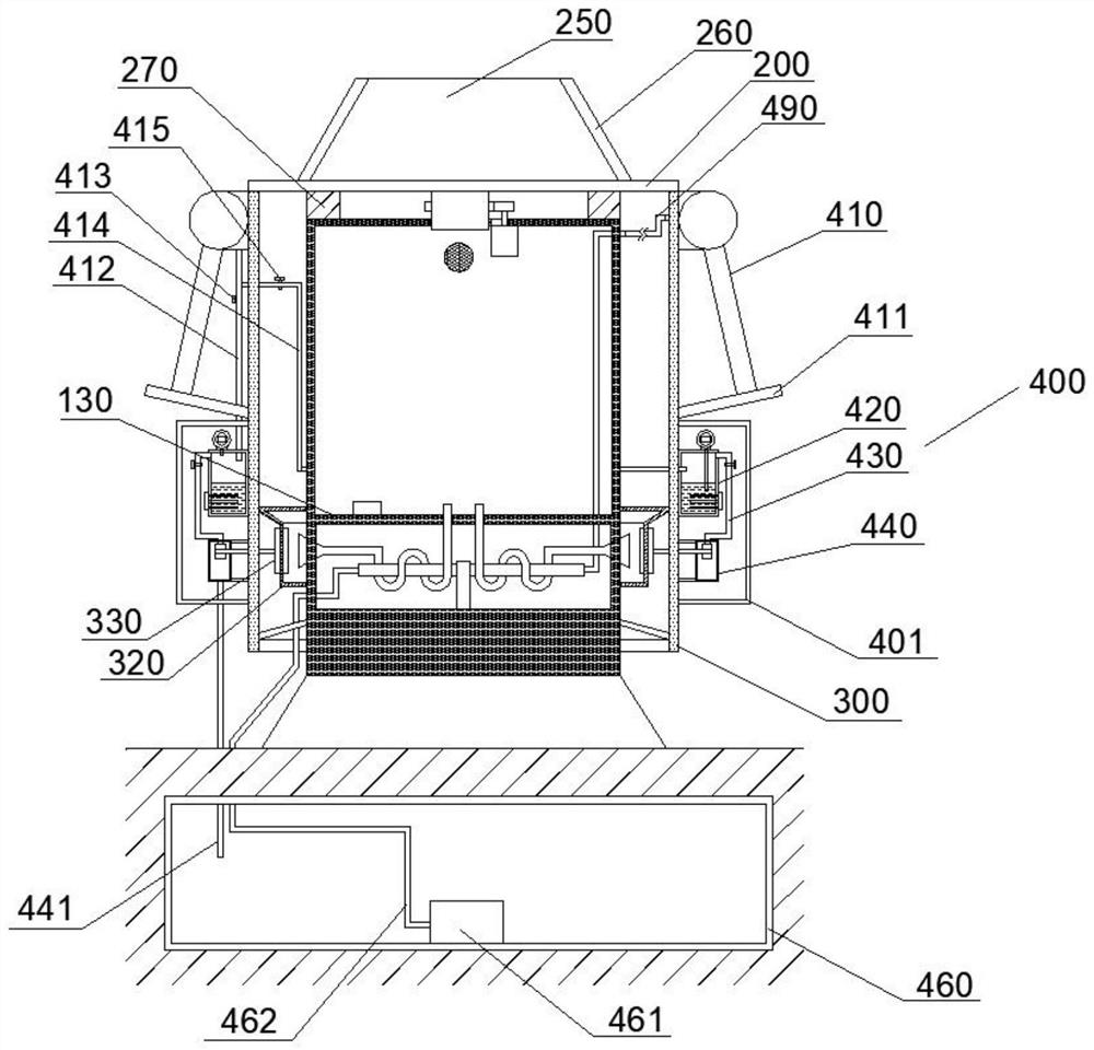
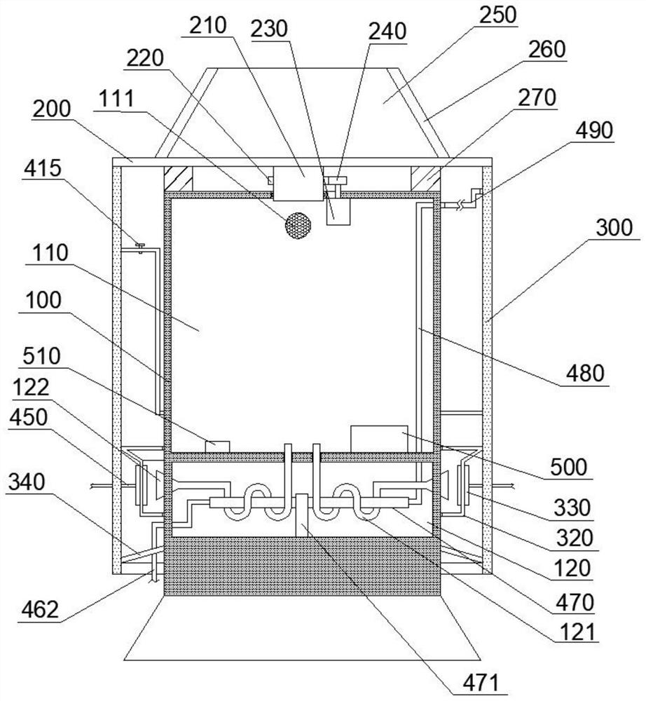
[0093] The transmission structure 400 also includes

[0094] The copper pipe 470 is arranged in the cooling chamber 120 through the positioning plate 471, and the part of the air inlet pipe 121 extending into the cooling chamber 120 is wound around the outer wall of the copper pipe 470 in a serpentine shape;

[0095] Outlet pipe 462, one end is connected to the water outlet end of water pump 461, the other end runs through the side wall of cooling chamber 120 and is connected to one end of copper pipe 470;

[0096] One end of the connecting pipe 480 is connected to the end of the copper pipe 470 away from the water outlet pipe 462, and the other end extends through the partition 130 and the side wall of the cooling chamber 120 into the heat insulation gap;

[0097] One end of the hose 490 is connected to the connecting pipe 480 in the heat insulation gap 490 , and the other end passes through the ...

Embodiment 3

[0100] As an optimization scheme of Embodiment 1, such as figure 2 , 3 , 4, 5,

[0101] The transmission structure 400 also includes

[0102] The insulation pipe 414 is arranged in the heat insulation gap in a serpentine shape. One end of the insulation pipe 414 runs through the side wall of the heat insulation board 300 and is connected to the drain pipe 412, and the other end of the heat insulation pipe 414 runs through the side wall of the heat insulation board 300 and the drain pipe 412. The heating box 420 is connected, and the connection between the insulation pipe 414 and the drain pipe 412 is located between the first solenoid valve 413 and the water outlet of the solar water heater 410 , and the insulation pipe 414 is provided with a second solenoid valve 415 .

[0103] This embodiment is implemented in such a way that when the temperature sensed by the temperature sensor 510 is lower than the minimum set value at night 20-5 o'clock in the morning, the first solenoid...

Embodiment 4

[0105] As the optimization scheme of embodiment three, such as figure 1 , 6 ,

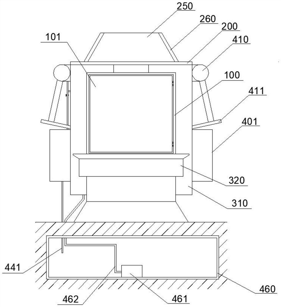
[0106] A baffle 310 is provided at the open end of the front end of the heat insulation gap, and the baffle 310 is connected with the rotating cover 200 and the heat insulation board 300, and the inner side wall of the baffle 310 is in sliding contact with the outer wall of the electrical cabinet 100;

[0107] The second heat dissipation net 301 is arranged on the heat insulation board 300 and is used to discharge the air in the heat insulation gap.

[0108] This embodiment is implemented in such a way that the front opening of the heat insulation gap is sealed by the provided baffle plate 310, so that when the heat is kept warm at night, the outflow of a large amount of heat energy in the heat insulation gap can be reduced and the heat preservation effect can be improved; wherein the second The cooling net 301 is used for cooling and exhausting during the day.

[0109] As a further optimization...


PUM


Abstract

The invention discloses outdoor electrical cabinet heat insulation and cooling treatment equipment and a cooling treatment method for an electric power system, and relates to the technical field of electrical cabinets, and an electric control box and a temperature sensor are both arranged in a mounting chamber; a first heat dissipation net is arranged on the side wall of the mounting chamber; oneend of an air inlet pipe penetrates through the partition plate and extends into the mounting chamber, and the other end extends into the cooling chamber; an air inlet cover penetrates through the side wall of the cooling chamber and is connected with one end, extending into the cooling chamber, of the air inlet pipe; a rotating column is rotationally arranged at the circle center of the upper endwall of the mounting chamber; a rotating cover is arranged on the rotating column; a solar power generation panel is arranged on the positioning table; the upper end wall of a heat insulation plate is connected with the rotating cover; a blocking cover is arranged on the outer side wall of the electrical cabinet in a sleeving manner, and the upper end of the outer side wall of the blocking coveris connected with the inner wall of the heat insulation plate; a fan is arranged on the side wall, corresponding to the heat insulation plate, of the blocking cover; and a transmission structure is arranged on the heat insulation plate. The equipment has the advantages of convenience in use, energy conservation, environmental protection, good cooling and cold resistance effects and the like.

Description

technical field [0001] The invention relates to the technical field of electrical cabinets, in particular to an outdoor electrical cabinet heat insulation and cooling treatment equipment and a cooling treatment method used in a power system. Background technique [0002] The electrical cabinet is a cabinet made of steel to protect the normal operation of components; the materials for making electrical cabinets are generally divided into two types: hot-rolled steel plate and cold-rolled steel plate; cold-rolled steel plate is softer than hot-rolled steel plate, and is more suitable for electrical appliances. Production of cabinets; electrical cabinets are widely used mainly in chemical industry, environmental protection industry, power system, metallurgical system, industry, nuclear power industry, fire safety monitoring, transportation industry and so on. [0003] Extreme weather occurs frequently in Northwest my country, and the temperature difference between day and night ...

Claims


Application Information

Patent Timeline
Patent Type & Authority Applications(China)
IPC IPC(8): H05K7/20
CPCH05K7/20136H05K7/20145
Inventor 方春
Owner 浙江安众科技有限公司
Why Eureka
Try Eureka