Differential pressure type multi-effect control dust collector

A vacuum cleaner and differential pressure technology, applied in the field of differential pressure multi-effect control vacuum cleaners, can solve the problems of affecting the vacuuming efficiency, inconvenient handling, breeding bacteria, etc., and achieve the effects of improving work efficiency, convenient handling and simplifying work.

Active Publication Date: 2021-02-12
钱才英
View PDF7 Cites 2 Cited by
  • Summary
  • Abstract
  • Description
  • Claims
  • Application Information

AI Technical Summary

Problems solved by technology

[0002] The working principle of the vacuum cleaner is that the motor of the vacuum cleaner rotates at a high speed, and the air is sucked in from the suction port to make a certain vacuum in the dust box. In the dust filter bag, the filtered air enters the motor through a layer of filter. This layer of filter is a protective barrier to prevent the dust bag from being broken and sucked into the motor. The air entering the motor flows out through the motor, and the existing vacuum cleaner cannot do this The suctioned garbage is separated according to the specifications, which causes subsequent processing inconvenience. The cleaning principle of the vacuum cleaner is to use suction to absorb dust and dry dirt, such as threads and paper scraps, from the floor, carpet, wall, furniture and other surfaces. , hair, etc., the current vacuum cleaners on the market will leave dust and dirt in the filter cover after use. If not processed in time, it will affect the vacuuming efficiency of the next use, and if the interior of the vacuum cleaner is not cleaned in time It may breed bacteria and cause serious damage to the human body. Therefore, it is necessary to design a pressure difference multi-effect control vacuum cleaner that is practical and can separate garbage by type.

Method used


Image

  • Differential pressure type multi-effect control dust collector
  • Differential pressure type multi-effect control dust collector
  • Differential pressure type multi-effect control dust collector

Examples


Embodiment Construction

[0034] The following will clearly and completely describe the technical solutions in the embodiments of the present invention with reference to the accompanying drawings in the embodiments of the present invention. Obviously, the described embodiments are only some, not all, embodiments of the present invention. Based on the embodiments of the present invention, all other embodiments obtained by persons of ordinary skill in the art without making creative efforts belong to the protection scope of the present invention.

[0035] see Figure 1-11 , the present invention provides technical solutions:

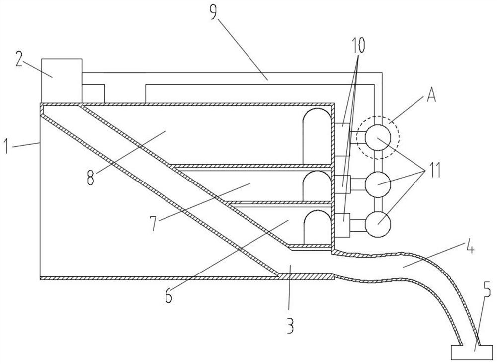
[0036] see figure 1 The dust suction channel assembly includes a main dust suction channel 3, an air suction pump 2 is arranged on one side of the shell body 1, the air suction pump 2 is connected to the main dust suction channel 3, and the main dust suction channel 3 runs through the top of the shell body 1 The end face and the side end face, the main dust suction channel 3 is i...


PUM


Abstract

The invention discloses a differential pressure type multi-effect control dust collector, which comprises a garbage classification assembly, wherein the garbage classification assembly is located on one side of a dust collection channel assembly, the garbage classification assembly is connected with the dust collection channel assembly through a pipeline, a garbage treatment assembly is arranged on one side of the garbage classification assembly, and the garbage treatment assembly is connected with the garbage classification assembly in a sliding manner; and the self-cleaning mechanism comprises a self-cleaning pipeline assembly, and the self-cleaning pipeline assembly is in pipeline connection with a garbage distribution assembly and the dust collection channel assembly. By arranging themain dust collection channel, garbage dust can be adsorbed into the main dust collection channel through suction force of an air suction pump, then garbage of different masses can be classified and recycled through air suction ports in the rear portions of the dust collection cavities, and thus the treatment is more convenient; and by arranging a differential pressure control valve, the differential pressure control valve can be more stable in the using process due to the fact that the flowability of the non-Newtonian fluid is small.

Description

technical field [0001] The invention relates to the technical field of vacuum cleaners, in particular to a differential pressure multi-effect control vacuum cleaner. Background technique [0002] The working principle of the vacuum cleaner is that the motor of the vacuum cleaner rotates at a high speed, and the air is sucked in from the suction port to make a certain vacuum in the dust box. In the dust filter bag, the filtered air enters the motor through a layer of filter. This layer of filter is a protective barrier to prevent the dust bag from being broken and sucked into the motor. The air entering the motor flows out through the motor, and the existing vacuum cleaner cannot do this The suctioned garbage is separated according to the specifications, which causes subsequent processing inconvenience. The cleaning principle of the vacuum cleaner is to use suction to absorb dust and dry dirt, such as threads and paper scraps, from the floor, carpet, wall, furniture and other...

Claims


Application Information

Patent Timeline
Patent Type & Authority Applications(China)
IPC IPC(8): A47L5/36A47L9/00A47L9/02A47L9/24
CPCA47L5/36A47L9/00A47L9/02A47L9/248
Inventor 不公告发明人
Owner 钱才英
Why Eureka
Try Eureka