Automatic spraying equipment

An automatic spraying and equipment technology, applied in the direction of the spraying device, etc., can solve the problems of large interval distance, no protection of the rotating drive mechanism, and no overall protection, so as to achieve the effect of automatic loading and unloading and convenient positioning and clamping

Pending Publication Date: 2021-02-12
宁波祺瑞涂装设备有限公司
View PDF1 Cites 2 Cited by
  • Summary
  • Abstract
  • Description
  • Claims
  • Application Information

AI Technical Summary

Problems solved by technology

[0006] First, in the actual use process, the overall protective performance of the spraying production line is not good. The reason is that the conveyor belt does not have excellent protective performance as it discloses. protection, but the core part of the conveyor belt, that is, the transmission chain mechanism that drives the action of the roller group, is not protected as a whole; at the same time, the rotary drive mechanism that drives the clamping mechanism to rotate is not protected; in addition, the spraying production line is in the clamping Although there is a material receiving sleeve on the mechanism, there is a large distance between the material receiving sleeve and the conveying track with the inner cavity; in summary, in the actual use process, the paint or powder sprayed by the spray gun is easy to deposit On the transmission chain mechanism, rotary drive mechanism, and clamping mechanism, as the use time prolongs, especially if the transmission chain mechanism deposits thick paint or sprays powder, it will cause the transmission failure of the entire spraying production line;
[0007] Second, since the clamping mechanism and the conveyor belt are connected through the fixing method of the horizontal plate and the suspension plate, the upper end of the suspension plate is sleeved on the rotating shaft of the roller group. In the actual use process, the suspension plate will drive the clamping mechanism Swing occurs, and at the same time, since each clamping mechanism is driven by the suspension plate, the distance between two adjacent clamping mechanisms will change in real time during the swing process of the respective suspension plates, so that the manipulator cannot position and clamp workpiece

Method used


Image

  • Automatic spraying equipment
  • Automatic spraying equipment
  • Automatic spraying equipment

Examples


Embodiment Construction

[0033] The present invention will be further described in detail below in conjunction with the accompanying drawings and embodiments.

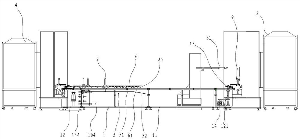
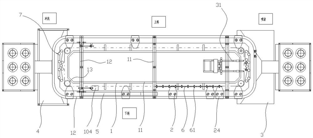
[0034] Such as Figures 1 to 4 As shown, the automatic spraying equipment in this implementation includes a frame 1, a transmission chain 6, a clamping mechanism 2, a cleaning room 4, a spraying room 3, and a spray gun 31.

[0035] where, please also see Figures 1 to 4 As shown, the transmission chain 6 is arranged on the frame 1 , and the frame 1 is provided with a plurality of clamping mechanisms 2 for clamping the workpiece 9 at intervals along the length direction of the transmission chain 6 . The transmission chain 6 drives the clamping mechanism 2 from the loading station of the transmission chain 6 through the spraying station and the unloading station in sequence. Each clamping mechanism 2 includes a mounting plate 24 , a body 21 disposed on the mounting plate 24 , and a clamping jig 22 disposed on the body 21 . A spray gun 31 insi...


PUM


Abstract

The invention discloses automatic spraying equipment which comprises a rack and a conveying chain, a plurality of clamping mechanisms are arranged on the rack, the conveying chain drives the clampingmechanisms to move, each clamping mechanism comprises a mounting plate, a body and a clamping jig, and a chain roller set is connected to the bottom of the conveying chain; an inner side baffle arranged in the length direction of the conveying chain is arranged on the portion, located on the inner side of the conveying chain, of the rack and covers the conveying chain, an outer side baffle arranged in the length direction of the conveying chain is arranged on the portion, located on the outer side of the conveying chain, of the rack, and a channel used for allowing the clamping jig to extend out is formed between the inner side baffle and the outer side baffle; and the inner end of each mounting plate is fixedly connected to the conveying chain, and the bottom of the outer end of each mounting plate is connected with the clamping roller set used for being arranged on the rack in a rolling mode. The automatic spraying equipment can effectively prevent paint or sprayed powder generated by a spray gun from being deposited on the conveying chain, clamping of a mechanical arm is facilitated, and automatic feeding and discharging are achieved.

Description

technical field [0001] The invention relates to the technical field of spraying, in particular to an automatic spraying equipment. Background technique [0002] In modern manufacturing, the painting operation of the outer surface of the workpiece has become a routine process requirement. And with the promotion of automation equipment, the automatic spraying production line has replaced the manual spraying operation in the traditional sense. [0003] For example, the Chinese invention with the existing publication number CN 105935636B discloses "A Spraying Production Line". The belt drives the clamping mechanism from the loading station of the conveyor belt through the spraying station and the unloading station in sequence, and then returns to the loading station. [0004] The conveyor belt includes a conveying track with an inner cavity. A roller set that can move in the conveying track is arranged in the conveying track. A suspension plate is arranged below the conveying ...

Claims


Application Information

Patent Timeline
IPC IPC(8): B05B13/02B05B15/50
CPCB05B13/0221B05B15/50
Inventor 邓以刚
Owner 宁波祺瑞涂装设备有限公司
Why Eureka
Try Eureka