Intelligent manufacturing device used for steel cutting
An intelligent manufacturing and steel technology, applied in the field of manufacturing devices, can solve the problems of threats and dangers to people, and achieve the effects of preventing sparks from splashing, increasing service life, and increasing safety
- Summary
- Abstract
- Description
- Claims
- Application Information
AI Technical Summary
Problems solved by technology
Method used
Image
Examples
Embodiment 1
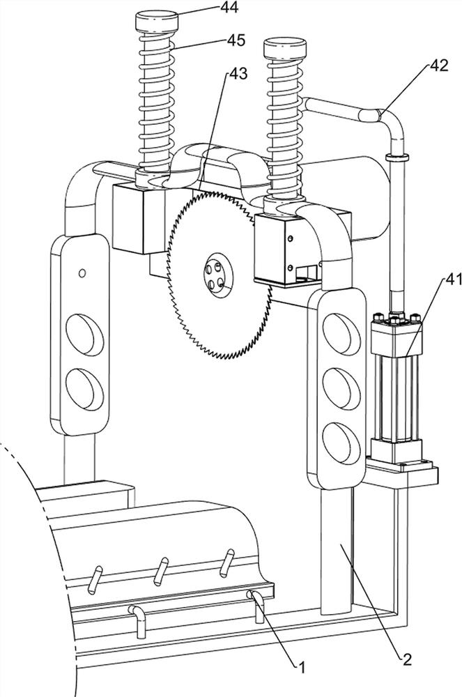
[0029] Such as figure 1 As shown, an intelligent manufacturing device for steel cutting includes a base 1, a first support rod 2, a roller 3, a cutting and separating mechanism 4 and a water spray mechanism 5, and the left sides of the two bases 1 are provided with a first Support rods 2, rollers 3 are evenly rotated on the upper sides of the two bases 1, a cutting and separating mechanism 4 is provided between the upper sides of the two first support rods 2, and the side of the two first support rods 2 is close to the rollers 3 A water spray mechanism 5 is provided.
[0030] When it is necessary to cut the steel, the staff first places the steel on the roller 3, and then starts the cutting and separating mechanism 4, so that the cutting and separating mechanism 4 moves downward to cut the steel below, and at the same time, the cutting and separating mechanism 4 drives the water spray The mechanism 5 sprays water to cool down the cutting and separating mechanism 4 during cutt...
Embodiment 2
[0032] Such as figure 2 , image 3 and Figure 4 As shown, an intelligent manufacturing device for steel cutting, on the basis of Embodiment 1, the cutting and separating mechanism 4 includes a cylinder 41, a connecting rod 42, a cutting machine 43, a guide rod 44 and a first spring 45, and the rear A cylinder 41 is installed on the left side of the top of the base 1, and a connecting rod 42 is arranged on the top of the telescopic rod of the cylinder 41. A cutting machine 43 is slidably arranged between the two first support rods 2 tops near one side, and the upper end of the connecting rod 42 is connected to the cutting machine. 43 is connected at the top, and both sides of the cutting machine 43 are provided with guide rods 44. The guide rods 44 are slidably connected with the first support rod 2, and the first springs 45 are sleeved on the two guide rods 44. The first springs 45 is a compression spring, and the two ends of the first spring 45 are respectively connected ...
Embodiment 3
[0037] Such as Figure 5 , Figure 6 , Figure 7 and Figure 8 As shown, an intelligent manufacturing device for steel cutting, on the basis of Embodiment 1 and Embodiment 2, also includes a feeding mechanism 6, and the feeding mechanism 6 includes a rack 61, a first rotating shaft 62, a first Gear 63, first transmission assembly 64, second shaft 65, bevel gear assembly 66, third shaft 67, fourth support rod 68, second gear 69, first drum 610 and second transmission assembly 611, cutting machine 43 left The side is provided with a rack 61, and the first supporting rod 2 on the front side is rotatably provided with a first rotating shaft 62, and the middle part of the first rotating shaft 62 is provided with a first gear 63, the first gear 63 is a one-way gear, and the first gear 63 and The rack 61 is meshed, the second shaft 65 is rotatably arranged on the second support rod 52 on the front side, the first transmission assembly 64 is arranged between the rear end of the fir...
PUM
 Abstract
Description
Claims
Application Information
 - R&D
- Intellectual Property
- Life Sciences
- Materials
- Tech Scout
- Unparalleled Data Quality
- Higher Quality Content
- 60% Fewer Hallucinations
Browse by: Latest US Patents, China's latest patents, Technical Efficacy Thesaurus, Application Domain, Technology Topic, Popular Technical Reports.
© 2025 PatSnap. All rights reserved.Legal|Privacy policy|Modern Slavery Act Transparency Statement|Sitemap|About US| Contact US: help@patsnap.com


