Wooden stick rotary grinding machine for manufacturing shovels

A technology of wooden sticks and machines, which is applied in the field of rotary grinding machines for wooden sticks used in the manufacture of shovels, can solve problems such as insufficient smoothness of grinding and inability to realize automatic loading and unloading, and achieve the effect of saving manpower

Pending Publication Date: 2021-02-12
李统
View PDF5 Cites 3 Cited by
  • Summary
  • Abstract
  • Description
  • Claims
  • Application Information

AI Technical Summary

Problems solved by technology

[0006] In order to overcome the shortcomings of the traditional grinding technology that the grinding is still not smooth enough to realize automatic loading and unloading, the technical

Method used


Image

  • Wooden stick rotary grinding machine for manufacturing shovels
  • Wooden stick rotary grinding machine for manufacturing shovels
  • Wooden stick rotary grinding machine for manufacturing shovels

Examples


Embodiment 1

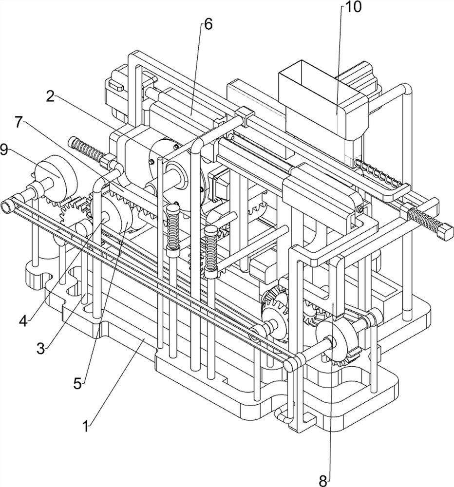
[0082] A rotary grinding machine with wooden sticks for making shovels, such as figure 1 As shown, it includes a base 1, a motor 2, a first fixed rod 3, a first rotating shaft 4, a first third gear 5, a load discharging and discharging mechanism 6, a translation and rotation fixing mechanism 7, and a translation and smoothing mechanism 8 And recovery mechanism 9, motor 2 is installed on the left rear portion on the base 1, the first fixed rod 3 is provided on the left side of the front side on the base 1, and the first fixed rod 3 is rotated to be provided with the first rotating shaft 4, the first rotating shaft 4 is connected with the output shaft of the motor 2, the first rotating shaft 4 is provided with the first third gear 5 on the front side, the upper front right part of the base 1 is provided with a loading and discharging mechanism 6, and the upper front side left part of the base 1 A translation and rotation fixing mechanism 7 is provided, a translation smoothing me...

Embodiment 2

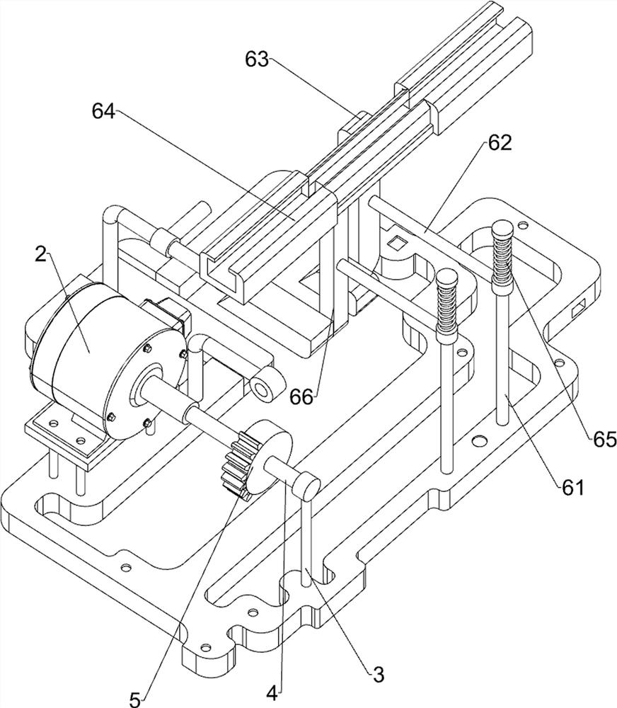
[0085] On the basis of Example 1, such as figure 2 , image 3 , Figure 4 , Figure 5 , Figure 6 and Figure 7 As shown, the loading, discharging and discharging mechanism 6 includes a second fixed rod 61, a sliding sleeve 62, an oblique connecting rod 63, a lifting plate 64, a first spring 65 and an oblique block 66. A second fixed rod 61 is symmetrically arranged, and a sliding sleeve 62 is slidably arranged on the second fixed rod 61. The rear portion of the sliding sleeve 62 on the right side is provided with an oblique connecting rod 63, and the front side of the upper part of the oblique connecting rod 63 is provided with a Lifting plate 64, the second fixed rod 61 top is covered with first spring 65, and the lower end of first spring 65 is connected with sliding sleeve 62, and the rear end of sliding sleeve 62 on the left side is provided with oblique block 66, and oblique type block 66 is placed with lifting Plate 64 is slidably connected.

[0086] People put t...


PUM


Abstract

The invention relates to a grinding machine, in particular to a wooden stick rotary grinding machine for manufacturing shovels. The wooden stick rotary grinding machine for manufacturing the shovels is quite smooth in grinding and capable of achieving automatic feeding and discharging. The wooden stick rotary grinding machine for manufacturing the shovels comprises a base, first fixed rods, firstrotating shafts and first one-third gears. A motor is mounted on the base. The first fixed rods are arranged on the base. The first rotating shafts are rotationally arranged on the first fixed rods, and the first rotating shafts are connected with an output shaft of the motor. The first one-third gears are arranged on the first rotating shafts. Through arrangement of a bearing, containing and discharging mechanism, the bearing, containing and discharging mechanism cooperates with a translation grinding mechanism, so that the effect of automatically grinding wooden sticks is achieved, and moremanpower is saved; and through arrangement of a recovery mechanism, the recovery mechanism can enable a grinding knife to move backwards to reset, and people can conduct the next wooden stick grindingoperation conveniently.

Description

technical field [0001] The invention relates to a grinding machine, in particular to a wooden stick rotary grinding machine for manufacturing shovels. Background technique [0002] A shovel is a kind of agricultural tool that can be used to shovel soil. Its long handle is mostly made of wood, and the top is equipped with a horizontal wooden stick for easy handling. [0003] People use sandpaper to polish wooden sticks every day. This operation is not only inefficient, but also the small wooden thorns on the wooden sticks are easy to hurt the hands of the staff when grinding. At the same time, the surface of the polished wooden sticks is not It's smooth, doesn't sand well. [0004] Patent application number CN201720045474.7 discloses an automatic wood stick grinding machine, which includes a frame, on which a first support and a first driving member are provided, and a second support is provided on one side of the first support. The other side is provided with a third suppo...

Claims


Application Information

Patent Timeline
IPC IPC(8): B24B5/50B24B5/04B24B5/35B24B47/12B24B41/02B24B41/06
CPCB24B5/50B24B5/04B24B5/35B24B5/355B24B47/12B24B41/02B24B41/06
Inventor 李统
Owner 李统
Why Eureka
Try Eureka