A small log center punching integrated device

A technology for small logs and workbenches, which is used in transportation and packaging, conveyor objects, fixed drilling machines, etc., can solve the problems of different punching positions, inability to locate small logs, and affect processing, etc., and achieves simple operation, Manpower saving effect

Active Publication Date: 2022-07-05
NANJING LINGQUE INTELLIGENT MFG CO LTD
View PDF7 Cites 0 Cited by
  • Summary
  • Abstract
  • Description
  • Claims
  • Application Information

AI Technical Summary

Problems solved by technology

[0006] In order to overcome the disadvantages that the above-mentioned operation is relatively labor-intensive, and the small logs cannot be positioned well by hand during operation, it is easy to cause different punching positions and affect subsequent processing. The technical problem to be solved by the present invention is Provides an integrated device for punching holes in the center of small logs that is simple to operate, can save manpower, and can position small logs

Method used


Image

  • A small log center punching integrated device
  • A small log center punching integrated device
  • A small log center punching integrated device

Examples


Embodiment 1

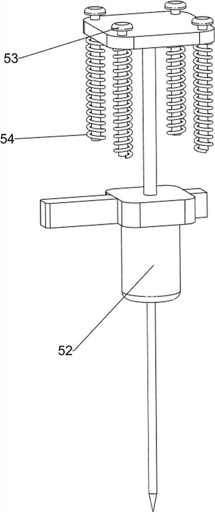
[0034] An integrated device for punching holes in the center of a small log, such as Figure 1 to Figure 4 As shown, it includes a bottom plate 1, a workbench 2 and a hydraulic cylinder 3, a workbench 2 is connected to the top of the bottom plate 1, a hydraulic cylinder 3 is installed on the right side of the top of the workbench 2, and also includes a feeding mechanism 4 and a punching mechanism 5, A feeding mechanism 4 is provided between the worktable 2 and the hydraulic cylinder 3 , and a punching mechanism 5 is provided on the worktable 2 , and the feeding mechanism 4 is connected with the punching mechanism 5 by transmission.

[0035] The feeding mechanism 4 includes a connecting block 41 , a material pushing long plate 42 , a U-shaped baffle 43 , and a discharging cylinder 44 , a connecting block 41 is connected to the telescopic rod of the hydraulic cylinder 3 , and the connecting block 41 is slidingly matched with the worktable 2 , the connecting block 41 is connected...

Embodiment 2

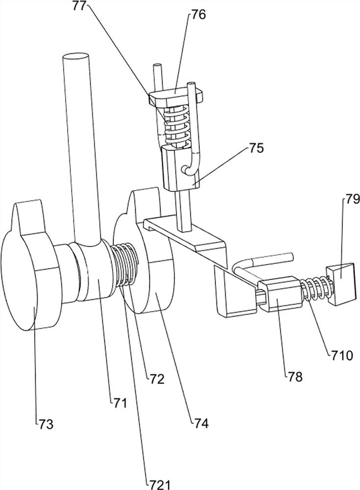
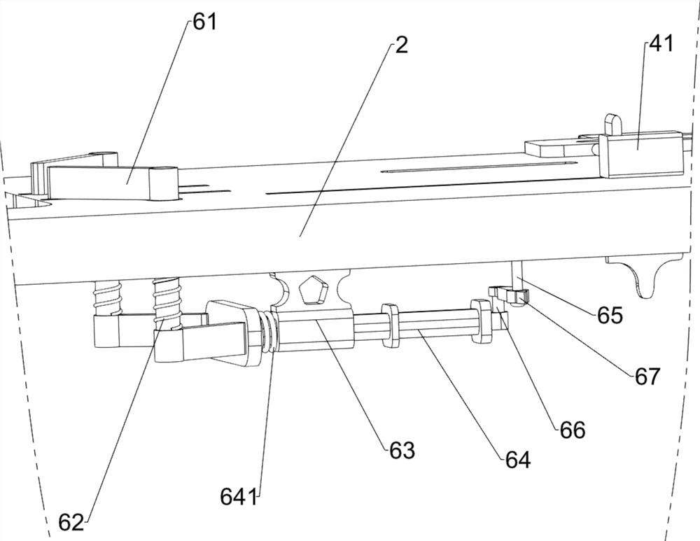
[0039] On the basis of Example 1, as Figure 5 to Figure 8 As shown, a clamping mechanism 6 and a clamping mechanism 7 are also included. The worktable 2 is provided with a clamping mechanism 6 and a clamping mechanism 7, and the clamping mechanism 6 and the clamping mechanism 7 are connected by transmission.

[0040] The clamping mechanism 6 includes a double-headed plate 61, a first torsion spring 62, a fixed guide block 63, a first push plate 64, a first rotating shaft 65, a second rotating shaft 66, a sliding link 67 and a large pressure spring 641. Both the front and rear sides of the table 2 are rotatably connected with a double-headed plate 61, a first torsion spring 62 is connected between the double-headed plate 61 and the worktable 2, a fixed guide block 63 is connected to the inner top of the worktable 2, and the inside of the fixed guide block 63 A first push plate 64 is slidably connected, the first push plate 64 cooperates with the double-headed plate 61, a large...

Embodiment 3

[0044] On the basis of Example 2, as Figures 9 to 10 As shown, it also includes a pushing mechanism 8, and the pushing mechanism 8 includes a third guide sleeve 81, a long connecting rod 82, a second push plate 83, a fourth compression spring 84, a second elastic dial 85 and a third elastic Dial block 86, a third guide sleeve 81 is connected to both the front and rear sides of the inner top of the workbench 2, a long connecting rod 82 is slidably connected to the third guide sleeve 81, and a second connecting rod 82 is connected between the right sides of the long connecting rods on both sides. Push plate 83, a fourth compression spring 84 is connected between the second push plate 83 and the third guide sleeve 81, the second push plate 83 is slidingly matched with the table 2, and the left side of the two long connecting rods 82 is connected with a second The elastic dial 85 and the second elastic dial 85 are slidably matched with the worktable 2 , and a third elastic dial 8...


PUM


Abstract

The invention relates to a punching device, in particular to an integrated device for central punching of a small log. The technical problem to be solved by the present invention is how to design a small log center punching integrated device that is easy to operate, can save manpower, and can position the small log. In order to solve the above-mentioned technical problems, the present invention provides such an integrated device for center punching of small round logs, which includes: a bottom plate, the top of which is connected with a workbench, and a hydraulic cylinder is installed on one side of the top of the workbench; a feeding mechanism, which The punching mechanism is arranged between the workbench and the hydraulic cylinder; the punching mechanism is arranged on the workbench, and the feeding mechanism is connected with the punching mechanism by transmission. According to the invention, the small log is punched through the cooperative operation of the feeding mechanism and the punching mechanism, so as to achieve the effect of punching the small log.

Description

technical field [0001] The invention relates to a punching device, in particular to an integrated device for central punching of a small log. Background technique [0002] With the continuous development of modern society and the continuous improvement of people's quality of life, wood is used in many places in modern society. Wood is a lignified tissue formed by plants that can grow secondary, such as trees and shrubs. These plants After the primary growth, the vascular cambium in the rhizome begins to move, and some manufacturers will cut the wood into small logs. After the cutting, the small logs need to be punched. [0003] At present, the method of punching the small log is usually to manually place the small log on the punching device. After the placement is completed, the user operates the punching device to punch the hole. After the punching is completed, the small log is replaced. The above method is more complicated and labor-intensive, and the small log cannot be...

Claims


Application Information

Patent Timeline
Patent Type & Authority Patents(China)
IPC IPC(8): B27C3/02B65G47/82
CPCB27C3/02B65G47/82B65G2201/0282Y02P70/10
Inventor 王艳娜
Owner NANJING LINGQUE INTELLIGENT MFG CO LTD
Why Eureka
Try Eureka